


Cable Pinouts C - 7
– Shell connector not crimped onto AUI cable braid.
– Ribbon cables in computers not shielded or improperly
mounted.
❑ Broken pair wires or unseated AUI connector pin.
❑ Improper pairing:
– Verify that signal and power wires are paired, that is,
Transmit + paired with Transmit -, etc.
❑ Individual pairs not individually shielded (Ethernet V1.0 type cable).
Recommendations
❑ The Bridge Module is fully compatible with IEEE 802.3 and Ethernet
V2.0. The use of Ethernet V1.0 AUI cables and transceivers is not
recommended.
❑ The Bridge Module accepts either 802.3 or V2.0 AUI cables. The
proper AUI cable should be used for the appropriate transceiver
being used. That is, if an 802.3 transceiver is used, then use an 802.3
AUI cable.
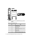
RS-232 Cables
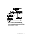
When you first connect your terminal to the Bridge Module management
interface, make sure it is properly set for asynchronous serial
communication. Figure C-2 illustrates the RS-232 connector on the front
panel of the Bridge Module and shows the proper pinouts for a crossover
RS-232 cable (either female-female or female-male). Table C-4 shows the
proper pinouts for the RS-232 cable.