


2 - 8 ONline Ethernet Bridge Module Installation and Operation Guide
Related Features
The following sections describe functions that allow you to:
❑ check the module's channel assignment and LED functionality
❑ remotely manage the Bridge Module from another device
LED and Channel Verification
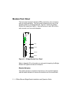
The ONline Controller Module is equipped with an LED check button on the
front panel. The LED check button has two functions: it causes all LEDs in
all modules in the concentrator to light, and it causes each module to
identify the channel to which it is assigned. When you press this button,
the module initiates a test to all modules in the concentrator. Any LED that
does not light is defective.
After the five seconds elapse, the diagnostic continues with a channel
check of all modules. Each Port Status LEDs should respond by blinking the
number of times to correspond with the channel to which it is assigned.
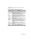
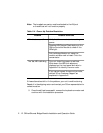
The channel check sequence repeats five times. Table 2-3 explains the
channel check codes.
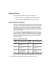
Table 2-3. Channel Check Codes
Port 1
LEDs
Port 1 Configuration
Port 2
LEDs
Port 2 Configuration
1 Blink Port is configured for
channel 1
1 Blink Port is configured for
channel 1
2 Blinks Port is configured for
channel 2
2 Blinks Port is configured for
channel 2
4 Blinks Port is configured to
the AUI connector
3 Blinks Port is configured for
channel 3
Off Port is isolated Off Port is isolated