


2 - 14
Chapter 2 Operation of Diag.
4.2 IOT Diag.
4.2.1 Digital Input (DI) Test
This function checks whether the DI components operate normally or not.
The DI test is performed for all the DI components.
Exit operation of the DI test makes the control panel display the Customer diag. function menu.
During the DI test, other Customer diag. functions can not be performed simultaneouly.
Therefore, the printer does not accept any operation except operations for the DI
components and exit operation of the DI test.
At the start of the DI test, number “ 0 ” is displayed on the control panel. This number is counted
up when a DI component is turned on from off, therefore it allows the user to know the component
is active.
4.2.2 Executing digital input (DI) test
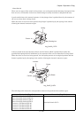
1) Turn off the power.
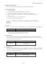
2) Turn on the power while holding down “ ” and “ ” keys.
3) Release the fingers from these keys when “Diagnosing...” is displayed.
4) The “Customer Mode” and “ESS Diag” are displayed. (Entered the Diag. mode.)
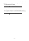
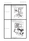
5) Press “ ” to select “IOT Diag”, and then press “ 3 ” key.
6) Press “ ” key to select “Digital Input”, and then press “ 3 ” key.
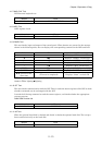
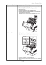
7) Press “ ” or “ ” key to select the test item.
8) Press “ 3 ” key twice to execute the test.
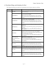
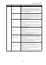
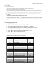
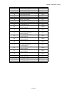
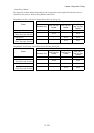
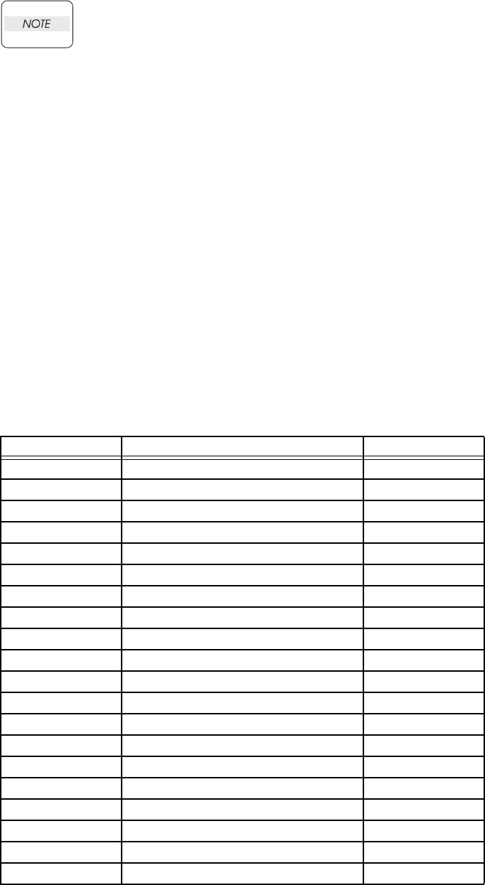
Parameters for the Digital Input Test are as follows.
Code(HEX) Code_DI Menu No.
00 FULL STACK SENSOR DI-0
01 DUP JAM SENSOR DI-1
02 EXIT SENSOR DI-2
03 REGI SENSOR DI-3
04 ROS READY (Internal signal) DI-4
05 FUSER READY (Internal signal) DI-5
07 INTERLOCK OPEN DI-7
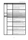
08 TONER CARTRIDGE SENSOR Y DI-8
09 TONER CARTRIDGE SENSOR M DI-9
0A TONER CARTRIDGE SENSOR C DI-a
0B TONER CARTRIDGE SENSOR K DI-b
0C NO TONER Y (Internal signal) DI-c
0D NO TONER M (Internal signal) DI-d
0E NO TONER C (Internal signal) DI-e
0F NO TONER K (Internal signal) DI-f
10 MSI NO PAPER DI-10
11 TRAY1 NO PAPER DI-11
12 TRAY2 NO PAPER DI-12
13 TRAY3 NO PAPER DI-13
15 TRAY1 LOW PAPER (not use) DI-15