3 - 4
Chapter 3 Removal and Replacement Procedures (RRPs)
1.2 Description of procedure
[RRP X.Y “AAAAA”] attached at the front of the procedure shows that the name of parts to be
assembled/disassembled is “AAAAA”.
“(PL X.Y.Z)” attached at the end of parts name in the procedure shows that the parts
corresponds to the plate (PL) “X.Y”, item “Z” of [Chapter 5 Parts list], and their shape and
fitting position can be checked in [Chapter 5 parts list].
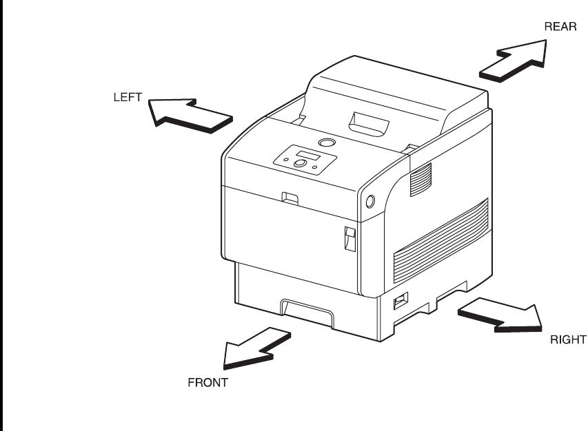
Description of direction shown below is used in the procedure.
TFront : Front direction when facing the front of device.
TRear : Rear direction when facing the front of device.
TLeft : Left direction when facing the front of device.
Tright : Right direction when facing the front of device.
Figure: Definition of Printer Orientation
Description of “[In the case of specification ***]” in the procedure shows that the work is
performed only on the device with relevant specification. (no work is performed on device with
irrelevant specification.)
“(RRP X.Y) used in or at the end of sentences in the procedure shows that related work
procedure is described in [RRP X.Y].
Screws in a diagram are supposed to be loosened and removed using a plus (+ screw driver),
unless otherwise specified.
Black arrow in a diagram shows the moving direction. Moreover, the order number attached
to the black arrows shows the order of movement.
Refer to [Chapter 4 Plug/Jack (P/J) Connector Locations] for the position of connector (P/J).
Ten03097KA


