


3 - 89
Chapter 3 Removal and Replacement Procedures (RRPs)
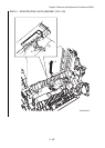
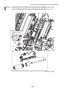
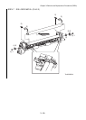
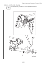
RRP4.6 REGISTRATION ASSEMBLY (PL4.2.1)
[Removal]
Before starting the following work, cover the entire DEVELOPER ASSEMBLY with paper
or the like so as to prevent toner in DEVELOPER ASSEMBLY from adhering on your
clothing.
1) Release the two hooks of the COVER ELEC (PL9.1.18), remove the COVER ELEC.
2) Disconnect the connector (P/J19) of the MACHINE CONTROL UNIT (MCU) (PL9.1.16).
3) Remove the harness of the HARNESS ASSY FRONTCLH (PL4.2.17) from the harness guide
of the printer.
4) Remove four screws (silver, tap, 10mm) that fix REGISTRATION ASSEMBLY to the printer.
5) Lift the gear of CLUTCH at the right side of REGISTRATION ASSEMBLY by approximately
5 mm to disengage the gear.
6) Move REGISTRATION ASSEMBLY to the left side and lift it up to remove.
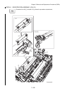
[Replacement]
1) Insert the gear of CLUTCH at the right side of REGISTRATION ASSEMBLY into the hole of
the printer to engage the gear.
2) Match the bosses at two locations on the printer with the holes of CLUTCH ASSY REGI,
insert it into the holes.
3) Attach REGISTRATION ASSEMBLY using four screws (silver, tap, 10mm).
4) Lay the harness of the HARNESS ASSY FRONTCLH to the harness guide of the printer.
5) Connect the connector (P/J19) of the MACHINE CONTROL UNIT (MCU).
6) Attach the COVER ELEC using the two hooks of the COVER ELEC.
Be sure to remove the paper covering DEVELOPER ASSEMBLY.