


3 - 110
Chapter 3 Removal and Replacement Procedures (RRPs)
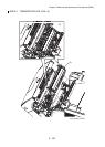
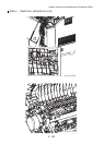
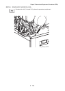
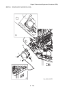
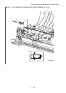
RRP5.5 DRIVE ASSY FUSER (PL5.2.25)
[Removal]
1) Remove TOP COVER FRAME. (RRP1.1)
2) Remove RIGHT FRONT COVER. (RRP1.8)
3) Remove RIGHT SIDE COVER. (RRP1.7)
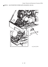
4) Remove DUPLEX HINGE LINK SPRING (PL5.1.6) on the right side of the printer.
5) Remove the hole at the center of DUPLEX HINGE LINK (PL5.1.7) on the right side of the
printer from the boss.
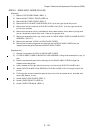
6) Remove the one screw (silver, provided with outer-teeth washer, 5mm) securing the ground
wire on the bottom plate of the printer. Take out the ground wire.
7) Remove three screws (silver, tap, 10mm) which fix DRIVE ASSY FUSER to INNER DUPLEX
ASSEMBLY (PL5.2.1).
8) Remove the connector (P/J521) on DRIVE ASSY FUSER.
9) Remove the harness and ground wire coming from the DRIVE ASSY FUSER from the
respective harness guide. Remove the DRIVE ASSY FUSER.
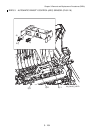
[Replacement]
1) Connect the connector (P/J521) on DRIVE ASSY FUSER.
2) Fix DRIVE ASSY FUSER to INNER DUPLEX ASSEMBLY using three screws (silver, tap, 10
mm).
3) Pass the harness and ground wire coming from the DRIVE ASSY FUSER through the
respective harness guides.
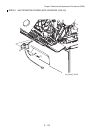
4) Insert the boss on the right side of the printer into the hole on DUPLEX HINGE LINK.
5) Attach DUPLEX HINGE LINK SPRING to DUPLEX HINGE LINK at the right side of the
printer.
6) Fix the ground wire on the bottom plate of the printer with one screw (silver, provided with
outer-teeth washer, 5 mm).
7) Attach RIGHT SIDE COVER. (RRP1.7)
8) Attach COVER FRONT R. (RRP1.8)
9) Attach COVER TOP MAIN. (RRP1.1)