7 – 11
Chapter 7 Wiring Diagrams and Signal Information
♦ Outline of SWITCH ASSY SIZE
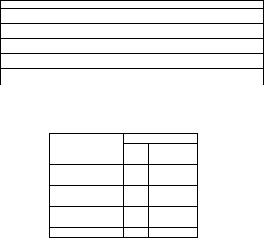
The paper size is determined by a combination of ON/OFF statuses of the upper, middle, and
lower switches of SWITCH ASSY SIZE.
ON: The actuator is pushing the switch.
Signal line name Description
CST1 SIZE0 SWITCH
ON(L)+3.3VDC
ON/OFF detection signal of SWITCH ASSY SIZE upper SW
CST1 SIZE1 SWITCH
ON(L)+3.3VDC
ON/OFF detection signal of SWITCH ASSY SIZE middle SW
CST1 SIZE2 SWITCH
ON(L)+3.3VDC
ON/OFF detection signal of SWITCH ASSY SIZE lower SW
CST1 NO PAPER
SENSED(H)+3.3VDC
Cassette paper detection signal by SENSOR PHOTO (No Paper
Sensor) (High:no paper)
CST1 FEED SOL ON(L)+24VDC ON/OFF control signal of SOLENOID FEED (Tray 1)
CST1 TURN CL ON(L)+24VDC ON/OFF control signal of CLUTCH ASSY TURN (Tray 1)
Paper size
Switches
Upper Middle Lower
LEGAL14" (SEF) ONONON
LEGAL13" (SEF) ON ON OFF
EXECUTIVE (SEF) ON OFF ON
B5 (SEF) ON OFF OFF
A4 (SEF) OFF ON ON
LETTER (SEF) OFF OFF ON
A5 OFF ON OFF
No cassette OFF OFF OFF


