7 – 18
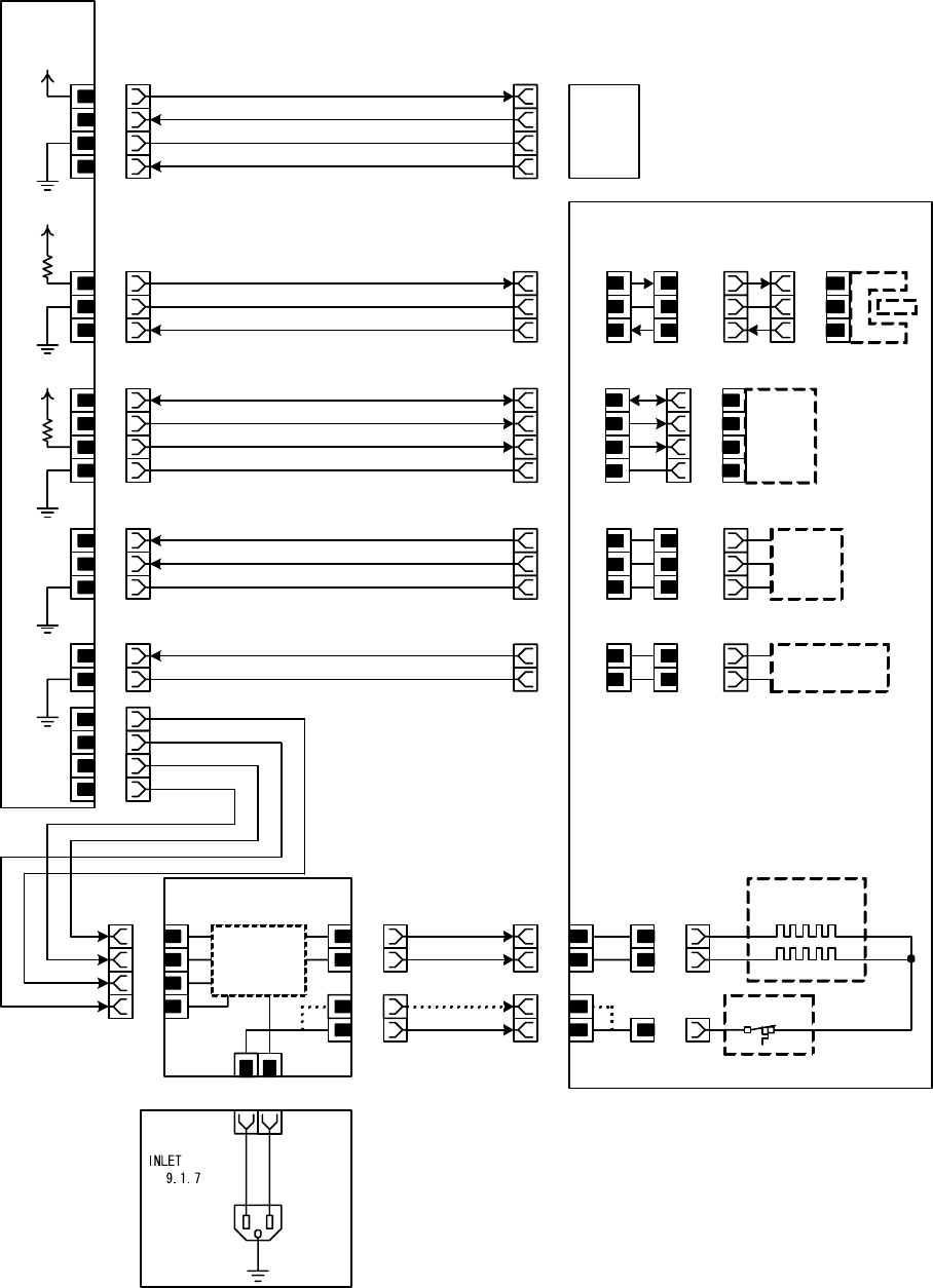
Chapter 7 Wiring Diagrams and Signal Information
§ 6 Fuser section
P/J160
1
2
HARNESS
ASSY AC
PL
Heater
Control
P/J162
4
1
LVPS
PL9.1.6
FUSER ASSY
PL5.1.1
AC N SUB
AC L(120V)
Heater
Thermostat
PWBA MCU
PL9.1.16
P/J36
6
J361
A7
A6
A5
J361
B3
P361
A1
A2
A3
P361
B4
7
8
P/J36
16
17 B1 B6
Exit Sensor
PULL UP +3.3VDC
SG
EXIT PAPER SENSED(L)+3.3VDC
STS
SG
FUSER_STS
+3.3VDC
P/J61
10
P/J165
9
Ten_Sec007_007FA
3
AC N MAIN
P/J36
15
14
13
J361
B4
B5
B6
P361
B3
B2
B1
NCS_VD
SG
Fuser NCS
NCS_VC
11
12
13
8
P361
A4
A5
A6
A7 1
2
3
P/J144
4
Fuser
EEPROM
2
AC L(230V)
2
3
1
P/J361
4
P/J36
9
10
11
12
SG
A1
A2
A3
J361
A4
+3.3VDC
EEPROM CLOCK
EEPROM DATA
P323
3
J323
1
2
1
2
3
P/J327
3
2
1
P/J24
4
3
2
1
J231
1
2
3
4
+5VDC
RHV
SG
TH2
SENSOR HUM
PL9.1.20
+5VDC
7
6
xHEAT2
HEAT2
HEAT1
xHEAT1
P331
1
2
3
J331
3
2
1
P322
2
1
J322
1
2
P3613
1
P3611
1
P3612
1
+3.3VDC
CN1
The CN1 is printed on the board.


