


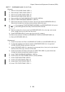

3 - 169
Chapter 3 Removal and Replacement Procedures (RRPs)
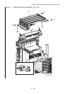
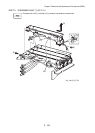
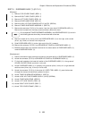
RRP7.7 DISPENSER ASSY (C) (PL7.2.3)
[Removal]
1) Remove TOP COVER FRAME. (RRP1.1)
2) Remove RIGHT SIDE COVER. (RRP1.7)
3) Remove LEFT SIDE COVER. (RRP1.12)
4) Remove COVER ASSY REAR. (RRP1.5)
5) Remove HIGH VOLTAGE POWER SUPPLY (HVPS). (RRP9.9)
6) Remove TONER DISPENSER ASSEMBLY. (RRP7.4)
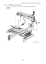
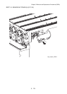
7) Remove the connector (P/J513) of the motor from the right side of DISPENSER ASSY (C).
Remove the harness from the clamp mounted directly above the motor.
Do not separate TONER DISPENSER ASSEMBLY and DISPENSER ASSY (C) too far in
the following process since they are connected with a harness.
8) Remove a screw (silver, 6 mm) that fixes DISPENSER ASSY (C) on the right, and a screw
(silver, taptgg, 10mm) on the left from the printer.
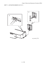
9) Slide DISPENSER ASSY (C) to the right and a little lift it upward.
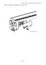
10) Remove the connector (P/J703) from SENSOR NO TONER on DISPENSER ASSY (C).
11) Remove DISPENSER ASSY (C).
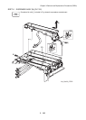
[Replacement]
1) Attach the connector (P/J703) to the SENSOR NO TONER on the DISPENSER ASSY (C).
2) Fit the hook located on the lower left section of DISPENSER ASSY (C) in the groove of
COVER HOLDER CRUM and slide it to the left.
3) Attach DISPENSER ASSY (C) in place by fixing one screw (silver, 6 mm) on its right side and
another screw (silver, tap, 10 mm) on its left side.
4) Attach the connector (P/J513) of the motor of HLDER TCRU ASSY (C), pass the harness
through the clamp mounted directly above the motor.
5) Attach TONER DISPENSER ASSEMBLY. (RRP7.4)
6) Attach HIGH VOLTAGE POWER SUPPLY (HVPS). (RRP9.9)
7) Attach COVER ASSY REAR. (RRP1.5)
8) Attach LEFT SIDE COVER. (RRP1.12)
9) Attach RIGHT SIDE COVER. (RRP1.7)
10) Attach TOP COVER FRAME. (RRP1.1)