


Copyright © 2001 G074-8627
Printed in China
UE USA
PRINTING A CONFIGURATION
PAG E
You can check if the printer works properly by
printing a configuration page.
However, you cannot check the connection
between the printer and the computer by printing
the configuration page.
Check that the power switch is turned on.
Press the
{
Menu
}
key.
"Menu" appears on the panel display.
Press the
{▲}
or
{▼}
key until the following
message appears on the panel display.
Menu:
List/Test Print
Press the
{
Enter
}
key.
The following message appears on the panel display.
List/Test Print:
Config. Page
Press the
{
Enter
}
key.
The test printing will start.
Important
❒ If you cannot complete the test printing correctly,
check if an error message appears on the panel
display. For more information about error
messages, see “Troubleshooting” in the Printer
Reference provided as a PDF file on the CD-ROM
labeled "Operating Instructions".
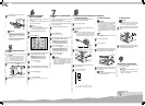
❖
Parallel connection
Important
❒ The parallel interface cable is not provided with
the printer. Make sure that the interface cable
you use is appropriate for your computer.
❒ The printer’s parallel connection is a standard
bi-directional interface. It requires a standard
36-pin parallel cable compliant with IEEE 1284
and an available parallel port on your computer.
❒ To avoid electrical interference, use a shielded
cable.
Note
❒ Do not use a parallel cable more than 2.5 meters
(8.2 feet) long.
Turn off the power switch.
Turn the computer off.
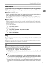
Attach the interface cable to the interface con-
nector of the printer. Secure the cable with the
metal fittings as shown in the illustration.
ZGDX115E
Attach the other end of the interface cable to
the interface connector of the computer. Se-
cure the cable.
Important
❒ Rating voltage of the parallel interface connector
for the computer ; Max. DC5V.
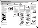
CONNECTING THE PRINTER TO A COMPUTER
Carefully slide the paper tray into the
printer until it stops.
Important
❒ Confirm that the setting of the paper size
dial matches the size and feed direction of
the paper in the tray. Otherwise, the printer
might be damaged or a printing problem
might occur.
❒ Do not slide the paper tray in and out with
force. If you do, the front and side paper
guides will move out of the place.
CONNECTING THE POWER
CORD
Caution
•
When you pull the plug out of the socket,
grip the plug to avoid damaging the cord
and causing a fire or an electric shock.
•
It is dangerous to handle the plug with
wet hands. An electric shock might occur.
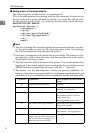
Check that the power switch is turned off.
ZGDH205E
Securely insert the power cord plug into the
wall socket.
SELECTING THE PANEL
DISPLAY LANGUAGE
Select a language following the procedures
described.
The message for the selected language will
appear on the panel display.
Note
❒ The default setting is English.
❒ If you want to use the English panel display, the
following procedures are unnecessary.
Check that the power switch is turned on.
Press the
{
Menu
}
key.
EnterForm Feed
Job Reset
On Line
Escape
Menu
Power Error Data In
"Menu" appears on the panel display.
Press the
{▲}
or
{▼}
key until the following
message appears on the panel display.
Menu:
Language
Press the
{
Enter
}
key.
Press the
{▲}
or
{▼}
key until the language
you want to select appears on the panel display.
Press the
{
Enter
}
key.
Press the
{
On Line
}
key.
The settings are applied and the ready message appears on the panel
display.
❖
Network connection
If your printer is installed with the Network Interface
Board, follow the procedures below.
Turn off the power switch.
Loop the network interface cable and attach
the ferrite core.
Note
❒ The network interface cable loop should be about
15 cm(6")(ቢ) from the end of the cable (on the
end closet to the printer). The ferrite core at the
end of the cable should be a ring type ferrite core.
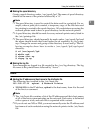
Attach the network interface cable to the
jack on the board.
ZGDT290E
Connect the other end of the network interface
cable to the network.
Turn on the power switch.
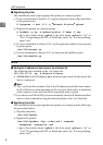
Check the LEDs on the ethernet port.
ZGDH260J
1
2
1 is lit when the printer is securely connected to the network.
2 is lit when 100BASE-TX is in use and not lit when 10BASE-T is in
use.
❖
USB connection
Important
❒ The USB interface cable is not provided with the
printer. Make sure that the USB interface cable
you use is appropriate for your computer.
Attach the USB interface cable to the USB
interface connector of the printer. Secure the
cable.
ZGDT300E
Attach the other end of the interface cable to
the USB interface connector of the computer
or the USB Hub. Secure the cable.
SETTING UP FOR PRINTING
Printing requires installation of a printer driver
for the operating system.
Reference
❒ See “Printer Drivers for This Printer” in the
Setup Guide.
❒ If you want to install options, see “Installing
Options” in the Setup Guide.