


e-STUDIO281c/351c/451c ADJUSTMENT June 2005 © TOSHIBA TEC
3 - 16
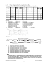
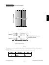
[B] Reproduction ratio adjustment of primary scanning direction
(1) While pressing [0] and [5] simultaneously, turn the power ON. → (Adjustment Mode)
(2) Place Test Chart No. TCC-1 on the original glass (with the arrow positioned at the left rear side).
(3) Press [FAX] → [START] to make a copy at the mode of A3/LD, 100%, Black and Text/Photo.
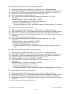
(4) Measure the distance A between M1 and M2 on the copy with a ruler.
(5) Check if the distance A is within 200±0.5 mm.
(6) If not, use the following procedure to change values and repeat step 3. to 5. above.
<Procedure>
(Adjustment Mode) → (Key in the code [405]) → [START]
→ (Key in a value (acceptable values: 0 to 255) with digital keys)
→ [ENTER] or [INTERRUPT] (Stored in memory)
* The larger the adjustment value is, the longer the distance A becomes (approx. 0.1 mm/step).
[C] Image location of primary scanning direction
(1) While pressing [0] and [5] simultaneously, turn the power ON. → (Adjustment Mode)
(2) Place Test Chart No. TCC-1 on the original glass (with the arrow positioned at the left rear side).
(3) Press [FAX] → [START] to make a copy at the mode of A4/LT, 100%, Black and Text/Photo.
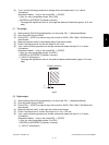
(4) Measure the distance B from the left paper edge to the 10 mm line of left grid pattern on the copy
with a ruler.
(5) Check if the distance B is within 10±0.5 mm.
(6) If not, use the following procedure to change values and repeat step 3. to 5. above.
<Procedure>
(Adjustment Mode) → (Key in code [306]) → [START]
→ (Key in a value (acceptable values: 0 to 255))
→ [ENTER] or [INTERRUPT] (Stored in memory)
* The larger the adjustment value is, the longer the distance B becomes (approx. 0.04 mm/
step).
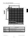
[D] Reproduction ratio of secondary scanning direction
(1) While pressing [0] and [5] simultaneously, turn the power ON. → (Adjustment Mode)
(2) Place Test Chart No. TCC-1 on the original glass (with the arrow positioned at the left rear side).
(3) Press [FAX] → [START] to make a copy at the mode of A4/LT, 100%, Black and Text/Photo.
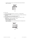
(4) Measure the distance C between M3 and M4 on the copy with a ruler.
(5) (Adjustment Mode) → (Key in the code [340]) → [START]
(6) If not, use the following procedure to change values and repeat step 3. to 5. above.
<Procedure>
(Adjustment Mode) → (Key in the code [340]) → [START]
→ (Key in a value (acceptable values: 0 to 255))
→ [ENTER] or [INTERRUPT] (Stored in memory)
* The larger the adjustment value is, the longer the distance C becomes (approx. 0.22 %/step).
[E] Image location of secondary scanning direction
(1) While pressing [0] and [5] simultaneously, turn the power ON. → (Adjustment Mode)
(2) Place Test Chart No. TCC-1 on the original glass (with the arrow positioned at the left rear side).
(3) Press [FAX] → [START] to make a copy at the mode of A4/LT, 100%, Black and Text/Photo.
(4) Measure the distance D from the top paper edge to the 10 mm line of top grid pattern on the copy
with a ruler.
(5) Check if the distance D is within 10±0.5 mm.