


e-STUDIO281c/351c/451c ERROR CODE AND SELF-DIAGNOSTIC MODE June 2005 © TOSHIBA TEC
2 - 46
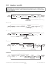
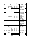
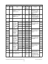
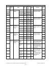
305 Scanner Image location adjustment
of secondary scanning
direction
(scanner section)
ALL 124
<92-164>
SYS When the value
increases by “1”, the
image shifts by approx.
0.137 mm toward the
trailing edge of the
paper.
1
306 Scanner Image location adjustment
of secondary scanning
direction
(scanner section)
ALL 113
<0-255>
SYS When the value
increases by “1”, the
image shifts by approx.
0.0423 mm toward the
front side of the paper.
1
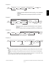
308 Scanner Distortion mode ALL - - Moves carriages to the
adjusting position.
(Ch.3.4.4)
6
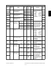
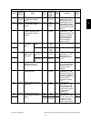
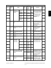
330-0 Image
control
Image quality
closed-loop
control con-
trast voltage
correction/
Mode 2 maxi-
mum number
of time cor-
rected
YALL3
<0-255>
M Sets the maximum cor-
rection number of time
of the contrast voltage
in the closed-loop con-
trol mode 2.
4
330-1 M ALL 3
<0-255>
M4
330-2 C ALL 3
<0-255>
M4
330-3 K ALL 3
<0-255>
M4
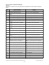
331-0 Image
control
Image quality
closed-loop
control laser
power correc-
tion/Mode 2
maximum
number of
time corrected
YALL2
<0-255>
M Sets the maximum cor-
rection number of time
of the laser power in the
closed-loop control
mode 2.
4
331-1 M ALL 2
<0-255>
M4
331-2 C ALL 2
<0-255>
M4
331-3 K ALL 2
<0-255>
M4
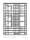
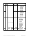
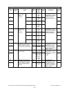
332-0 Image
control
Image quality
closed-loop
control con-
trast voltage
correction/
Mode 1 maxi-
mum number
of time cor-
rected
YALL1
<0-255>
M Sets the maximum cor-
rection number of time
of the contrast voltage
in the closed-loop con-
trol mode 1.
4
332-1 M ALL 1
<0-255>
M4
332-2 C ALL 1
<0-255>
M4
332-3 K ALL 1
<0-255>
M4
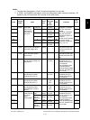
333-0 Image
control
Image quality
closed-loop
control laser
power correc-
tion/Mode 1
maximum
number of
time corrected
YALL1
<0-255>
M Sets the maximum cor-
rection number of time
of the laser power in the
closed-loop control
mode 1.
4
333-1 M ALL 1
<0-255>
M4
333-2 C ALL 1
<0-255>
M4
333-3 K ALL 1
<0-255>
M4
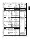
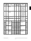
334 Image
control
Main charger grid calibra-
tion voltage 1 (low)
ALL 300
<210-
390>
M Transformer output cali-
bration of the main
charger grid bias. When
replacing the high-volt-
age transformer, the
values listed in attached
data sheet are entered.
(Unit: V)
1
335 Image
control
Main charger grid calibra-
tion voltage 2 (high)
ALL 1000
<900-
1100>
M1
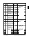
Adjustment mode (05)
Code
Classifi-
cation
Items
Func-
tion
Default
<Accept-
able
value>
RAM Contents
Pro-
cedur
e