


June 2005 © TOSHIBA TEC e-STUDIO281c/351c/451c ADJUSTMENT
3 - 95
3
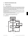
3.14.6 Registering the number of punch holes (Puncher unit)
This operation registers which puncher unit is attached to the IC on the punch driver PC board so that
the puncher unit can be identified by the finisher. For this reason, this operation must be performed
when the punch driver PC board has been replaced.
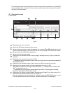
(1) Check that the power is OFF and then remove the rear cover of the puncher.
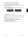
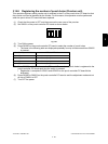
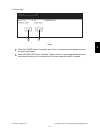
(2) Set SW601 on the punch controller PC board as shown below.
Fig.3-92
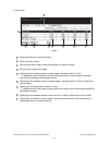
(3) Turn ON the power.
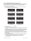
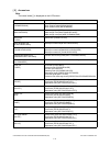
(4) Press SW602 on the punch controller PC board to select the number of punch holes.
• The items in the following table are displayed repeatedly from top to bottom each time SW602
is pressed.
(5) Press SW603 on the punch controller PC board. The number of punch holes is registered to the
punch controller PC board each time the switch is pressed.
• Registration is complete if LED601 and LED602 on the punch controller PC board blinks
alternately.
(6) Press SW602 or SW603 on the punch controller PC board to end the adjustment mode and set
all bits of SW601 to OFF.
(7) Turn OFF the power.
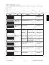
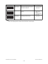
Number of punch holes LED601/LED602
2 hole (E) Blinks 1 times per cycle
2/3 hole (N) Blinks 2 times per cycle
4 hole (F) Blinks 3 times per cycle
4 hole (S) Blinks 4 times per cycle
ON
1 2 3 4