


e-STUDIO281c/351c/451c POWER SUPPLY UNIT June 2005 © TOSHIBA TEC
7 - 2
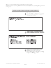
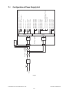
The followings are two output channels which are linked with the cover switch.
1) +5.1V
+5.1VD: CN466 Pin 11
Output to the LGC board
2) +24V
+24VD1: CN465 Pins 1 and 2
Output to the LGC board, Bridge unit (via LGC board)
+24VD1: CN469 Pins 1 and 2
Output to the PFP/LCF
+24VD1: CN470 Pin 1
Output to the power supply cooling fan
+24VD2: CN465 Pins 5 and 6
Output to the DRV board
+24VD3: CN467 Pins 1 and 2
Output to the RADF
+24VD4: CN467 Pins 10, 12 and 14
Output to the SLG board
+24VD5: CN468 Pin 2
Output to the finisher
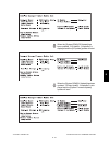
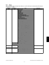
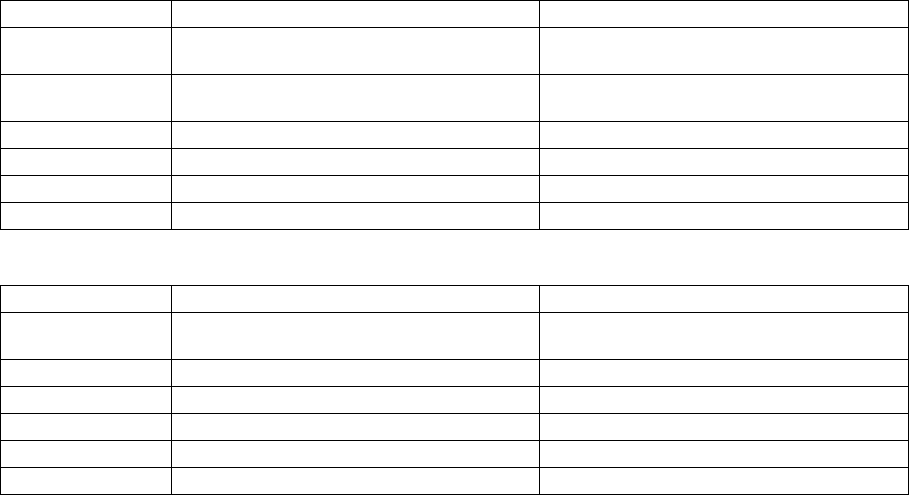
Output voltage by the type of connector
Main switch line
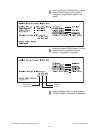
Cover switch line
Connector Destination Voltage
CN464 SYS board +3.3VA, +3.3VB, +5.1VA, +5.1VB, +12VA,
+12VB
CN466 LGC board, PFP/LCF (via LGC board),
Bridge unit (via LGC board)
+3.3VB, +5.1VB, +12VB
CN467 SLG board, RADF +3.3VB, 5.1VB
CN468 Finisher +5.1VB
CN469 FIL board +5.1VB
CN471 FAX unit +12VB
Connector Destination Voltage
CN465 LGC board, DRV board, PFP/LCF (via LGC
board), Bridge unit (via LGC board)
+24VD1, +24VD2
CN466 LGC board +5.1VD
CN467 SLG board, RADF +24VD3, +24VD4
CN468 Finisher +24VD5
CN469 PFP/LCF +24VD1
CN470 Power supply cooling fan +24VD1