


Appendix D Register Map and Descriptions
© National Instruments Corporation D-5 Lab-PC+ User Manual
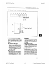
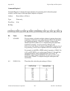
Command Register 1
Command Register 1 indicates the input channel to be read, the gain for the analog input
circuitry, and the range of the input signal (unipolar or bipolar).
Address: Base address + 00 (hex)
Type: Write-only
Word Size: 8-bit
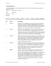
Bit Map:
7654 3 210
SCANEN GAIN2 GAIN1 GAIN0 TWOSCMP MA2 MA1 MA0
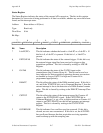
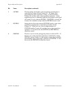
Bit Name Description
7 SCANEN This bit enables or disables multiple-channel scanning during data
acquisition. If this bit is set, analog channels MA<2..0> through 0
are sampled alternately. If this bit is cleared, a single analog
channel specified by MA<2..0> is sampled during the entire data
acquisition operation. See Programming Multiple A/D
Conversions with Channel Scanning in Appendix E, Register-Level
Programming, for the correct sequence involved in setting this bit.
For example, in the RSE or NRSE mode of operation, if MA<2..0>
is 011 and SCANEN is set, analog input Channels 3 through 0 are
sampled alternately during subsequent data conversions. If
SCANEN is then cleared (with MA<2..0> still set to 011), only
analog input Channel 3 is sampled during the subsequent data
conversions.
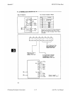
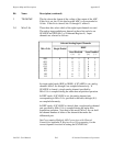
6-4 GAIN<2..0> These three bits select the gain setting as follows:
GAIN<2..0> Selected Gain
000 1
001 1.25
010 2
011 5
100 10
101 20
110 50
111 100