


Chapter 5 Calibration
© National Instruments Corporation 5-7 Lab-PC+ User Manual
1. Adjust the Analog Output Offset
Adjust the analog output offset by measuring the output voltage generated with the DAC set
at negative full-scale (0). This output voltage should be V
-fs
±0.5 LSB. For bipolar output,
V
-fs
= -5 V, and 0.5 LSB = 1.22 mV.
For analog output Channel 0:
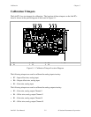
a. Connect the voltmeter between DAC0 OUT (pin 10 on the I/O connector) and AGND
(pin 11).
b. Set the analog output channel to -5 V by writing -2,048 to the DAC.
c. Adjust trimpot R2 until the output voltage read is -5 V.
For analog output Channel 1:
a. Connect the voltmeter between DAC1 OUT (pin 12 on the I/O connector) and AGND
(pin 11).
b. Set the analog output channel to -5 V by writing -2,048 to the DAC.
c. Adjust trimpot R4 until the output voltage read is -5 V.
2. Adjust the Analog Output Gain
Adjust the analog output gain by measuring the output voltage generated with the DAC set at
positive full-scale (4,095). This output voltage should be V
+fs
±0.5 LSB. For bipolar output,
V
+fs
= +4.99756 V, and 0.5 LSB = 1.22 mV.
For analog output Channel 0:
a. Connect the voltmeter between DAC0 OUT (pin 10 on the I/O connector) and AGND
(pin 11).
b. Set the analog output channel to +4.99756 V by writing 2,047 to the DAC.
c. Adjust trimpot R1 until the output voltage read is +4.99756 V.
For analog output Channel 1:
a. Connect the voltmeter between DAC1 OUT (pin 12 on the I/O connector) and AGND
(pin 11).
b. Set the analog output channel to +4.99756 V by writing 2,047 to the DAC.
c. Adjust trimpot R3 until the output voltage read is +4.99756 V.