


Chapter 2 Configuration and Installation
© National Instruments Corporation 2-9 Lab-PC+ User Manual
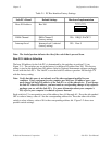
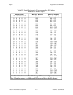
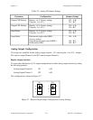
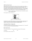
Table 2-4. Analog I/O Jumper Settings
Parameter Configuration Jumper Settings
Output CH0 Polarity Bipolar: ±5 V (factory setting)
Unipolar: 0 to 10 V
W1: A-B
W1: B-C
Output CH1 Polarity Bipolar: ±5 V (factory setting)
Unipolar: 0 to 10 V
W2: A-B
W2: B-C
Input Range Bipolar: ±5 V (factory setting)
Unipolar: 0 to 10 V
W3: A-B
W3: B-C
Input Mode Referenced single-ended (RSE)
(factory setting)
Nonreferenced single-ended (NRSE)
Differential (DIFF)
W4: A-B
W4: B-C
W4: B-C
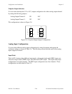
Analog Output Configuration
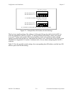
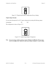
Two ranges are available for the analog outputs–bipolar: ±5 V and unipolar: 0 to 10 V. Jumper
W1 controls output Channel 0, and W2 controls output Channel 1.
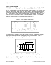
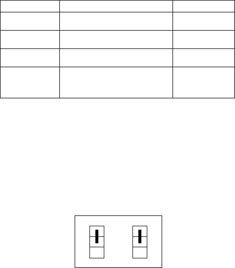
Bipolar Output Selection
You can select the bipolar (±5 V) output configuration for either analog output channel by setting
the following jumpers:
Analog Output Channel 0 W1 A-B
Analog Output Channel 1 W2 A-B
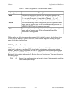
This configuration is shown in Figure 2-7.
•
•
•
A
B
C
W1
Channel 0
B
U
•
•
•
A
B
C
W2
Channel 1
B
U
Figure 2-7. Bipolar Output Jumper Configuration (Factory Setting)