


Configuration and Installation Chapter 2
Lab-PC+ User Manual 2-4 © National Instruments Corporation
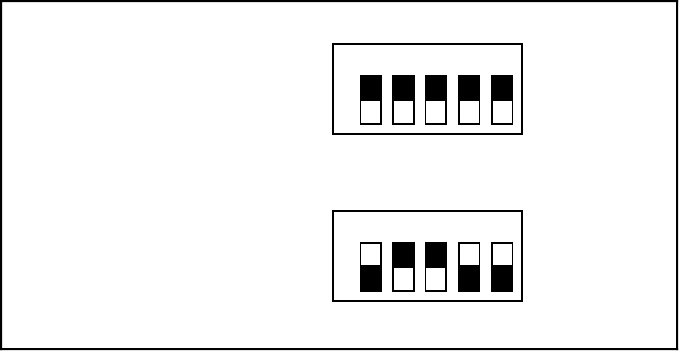
A9
A8
A7
A6
A5
1 2 3 4 5
O
N
O
F
F
U1
This side down for 0 —
This side down for 1 —
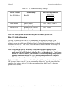
A. Switches Set to Base I/O Address of Hex 000
A9
A8
A7
A6
A5
1 2 3 4 5
O
N
O
F
F
U1
This side down for 0 —
This side down for 1 —
B. Switches Set to Base I/O Address of Hex 260 (Factory Setting)
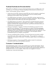
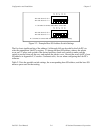
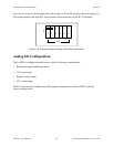
Figure 2-2. Example Base I/O Address Switch Settings
The five least significant bits of the address (A4 through A0) are decoded by the Lab-PC+ to
select the appropriate Lab-PC+ register. To change the base I/O address, remove the plastic
cover on U1; press each switch to the desired position; check each switch to make sure the
switch is pressed down all the way; and replace the plastic cover. Record the new Lab-PC+ base
I/O address in Appendix F, Customer Communication, for use when configuring the Lab-PC+
software.
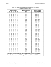
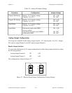
Table 2-2 lists the possible switch settings, the corresponding base I/O address, and the base I/O
address space used for that setting.