


Chapter 3 Signal Connections
© National Instruments Corporation 3-21 Lab-PC+ User Manual
Timing Connections
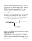
Pins 38 through 48 of the I/O connector are connections for timing I/O signals. The timing I/O
of the Lab-PC+ is designed around the 8253 Counter/Timer integrated circuit. Two of these
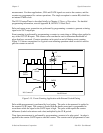
integrated circuits are employed in the Lab-PC+. One, designated 8253(A), is used exclusively
for data acquisition timing, and the other, 8253(B), is available for general use. Pins 38 through
40 carry external signals that can be used for data acquisition timing in place of the dedicated
8253(A). These signals are explained in the next section, Data Acquisition Timing Connections.
Pins 41 through 48 carry general-purpose timing signals from 8253(B). These signals are
explained under General-Purpose Timing Signal Connections and General-Purpose
Counter/Timing Signals later in this chapter.
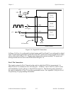
Data Acquisition Timing Connections
Counter 0 on the 8253(A) Counter/Timer (referred to as A0) is used as a sample interval counter
in timed A/D conversions. Counter 1 on the 8253(A) Counter/Timer (referred to as A1) is used
as a sample counter in conjunction with Counter 0 for data acquisition. These counters are not
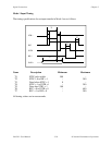
available for general use. In addition to counter A0, EXTCONV* can be used to externally time
conversions. See Appendix E, Register-Level Programming, for the programming sequence
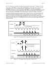
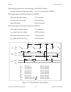
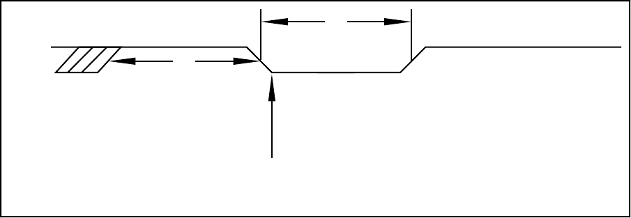
needed to enable this input. Figure 3-9 shows the timing requirements for the EXTCONV*
input. An A/D conversion is initiated by a falling edge on the EXTCONV*.
A/D Conversion starts within
125 nsec from this point.
EXTCONV*
t
w
250 nsec minimum
V
IH
V
IL
t
w
t
w
Figure 3-9. EXTCONV* Signal Timing
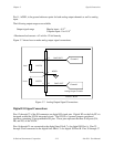
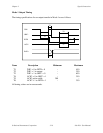
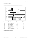
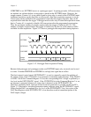
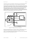
Another external control, EXTTRIG, is used for either starting a data acquisition sequence or
terminating an ongoing data acquisition sequence, depending on the settings of the HWTRIG and
PRETRIG bits in the Command Registers.
If HWTRIG is set, EXTTRIG serves as an external trigger to start a data acquisition sequence.
In this mode, posttrigger mode, the sample interval counter is gated off until a rising edge is
sensed on the EXTTRIG line. EXTCONV*, however, is enabled on the first rising edge of
EXTCONV*, following the rising edge on the EXTTRIG line. Further transitions on the
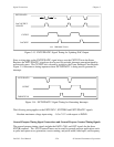
EXTTRIG line have no effect until a new data acquisition sequence is established. Figures 3-10