


Signal Connections Chapter 3
Lab-PC+ User Manual 3-16 © National Instruments Corporation
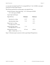
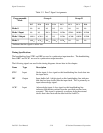
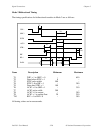
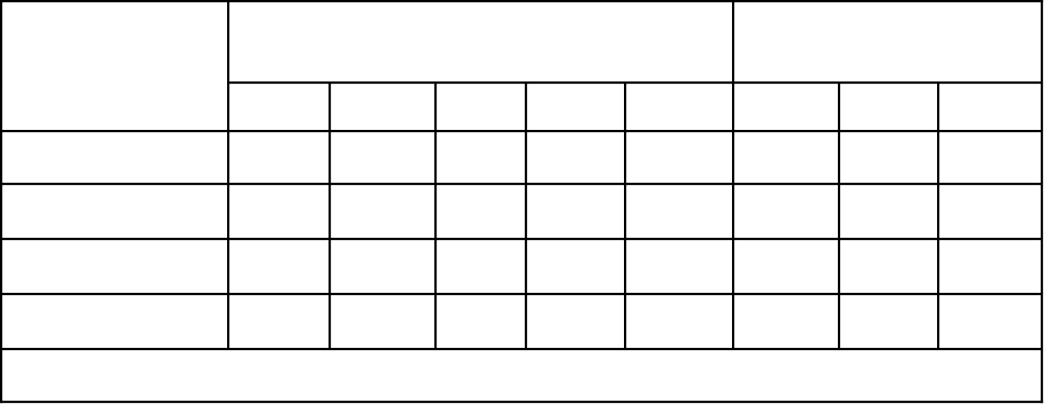
Table 3-2. Port C Signal Assignments
Programmable
Mode
Group A Group B
PC7 PC6 PC5 PC4 PC3 PC2 PC1 PC0
Mode 0
I/O I/O I/O I/O I/O I/O I/O I/O
Mode 1 Input
I/O I/O IBF
A
STB
A
* INTR
A
STB
B
* IBFB
B
INTR
B
Mode 1 Output
OBF
A
* ACK
A
* I/O I/O INTR
A
ACK
B
* OBF
B
* INTR
B
Mode 2
OBF
A
* ACK
A
* IBF
A
STB
A
* INTR
A
I/O I/O I/O
*Indicates that the signal is active low.
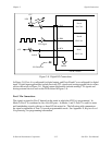
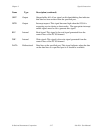
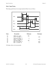
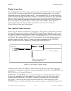
Timing Specifications
The handshaking lines STB* and IBF are used to synchronize input transfers. The handshaking
lines OBF* and ACK* are used to synchronize output transfers.
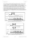
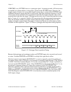
The following signals are used in the timing diagrams shown later in this chapter:
Name Type Description
STB* Input Strobe input–A low signal on this handshaking line loads data into
the input latch.
IBF Output Input buffer full–A high signal on this handshaking line indicates
that data has been loaded into the input latch. This is primarily an
input acknowledge signal.
ACK* Input Acknowledge input–A low signal on this handshaking line
indicates that the data written from the specified port has been
accepted. This signal is primarily a response from the external
device that it has received the data from the Lab-PC+.