


Chapter 3 Signal Connections
© National Instruments Corporation 3-23 Lab-PC+ User Manual
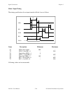
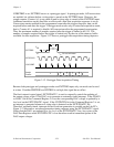
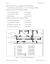
If PRETRIG is set, EXTTRIG serves as a pretrigger signal. In pretrigger mode, A/D conversions
are enabled via software before a rising edge is sensed on the EXTTRIG input. However, the
sample counter, Counter A1, is not gated on until a rising edge is sensed on the EXTTRIG input.
Additional transitions on this line have no effect until a new data acquisition sequence is set up.
Conversions remain enabled for the programmed count after the trigger; therefore, data can be
acquired before and after the trigger. Pretrigger mode works only in controlled acquisition mode,
that is, Counter A1 is required to disable A/D conversions after the programmed count expires.
Thus, the maximum number of samples acquired after the trigger is limited to 65,535. The
number of samples acquired before the trigger is limited only by the size of the memory buffer
available for data acquisition. Figure 3-12 shows a pretrigger data acquisition timing sequence.
t
w
50 nsec minimum
EXTTRIG
EXTCONV*
CONVERT
Sample
Counter
V
IH
V
IL
4
t
w
t
w
3210
Figure 3-12. Pretrigger Data Acquisition Timing
Because both pretrigger and posttrigger modes use EXTTRIG input, only one mode can be used
at a time. If neither PRETRIG nor HWTRIG is set high, this signal has no effect.
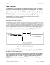
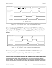
The final external control signal, EXTUPDATE*, is used to externally control the updating of
the output voltage of the 12-bit DACs or to generate an externally timed interrupt. If the LDAC0
or LDAC1 bit in the Command Register 2 is set, the corresponding DAC voltage is updated by a
low level on the EXTUPDATE* signal. If the CNTINTEN bit in the Command Register 3 is set,
an interrupt is generated whenever a rising edge is detected on the EXTUPDATE* bit.
Therefore, externally timed, interrupt-driven waveform generation is possible on the Lab-PC+.
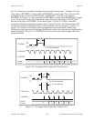
Figure 3-13 illustrates a waveform generation timing sequence using the EXTUPDATE* signal.
Notice that the DACs are updated by a low level on the EXTUPDATE* line. Any writes to the
DAC Data Registers while EXTUPDATE* is low therefore result in immediate update of the
DAC output voltages.