


Register-Level Programming Appendix E
Lab-PC+ User Manual E-28 © National Instruments Corporation
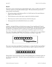
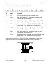
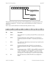
Port C status-word bit definitions for input (Port A and Port B):
76543210
I/O I/O IBFA INTEA INTRA INTEB IBFB INTRB
Bit Name Description
7-6 I/O Extra I/O status lines when Port A is in Mode 1 input.
5 IBFA Input buffer full for Port A. High indicates that data has been
loaded into the input latch for Port A.
4 INTEA Interrupt enable bit for Port A. Enables interrupts from the 8255A
for Port A. Controlled by bit set/reset of PC4.
3 INTRA Interrupt request status for Port A. When INTEA is high and IBFA
is high, this bit is high, indicating that an interrupt request is
asserted.
2 INTEB Interrupt enable bit for Port B. Enables interrupts from the 8255A
for Port B. Controlled by bit set/reset of PC2.
1 IBFB Input buffer full for Port B. High indicates that data has been
loaded into the input latch for Port B.
0 INTRB Interrupt request status for Port B. When INTEB is high and IBFB
is high, this bit is high, indicating that an interrupt request is
asserted.
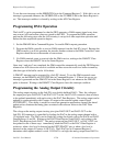
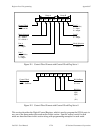
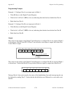
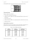
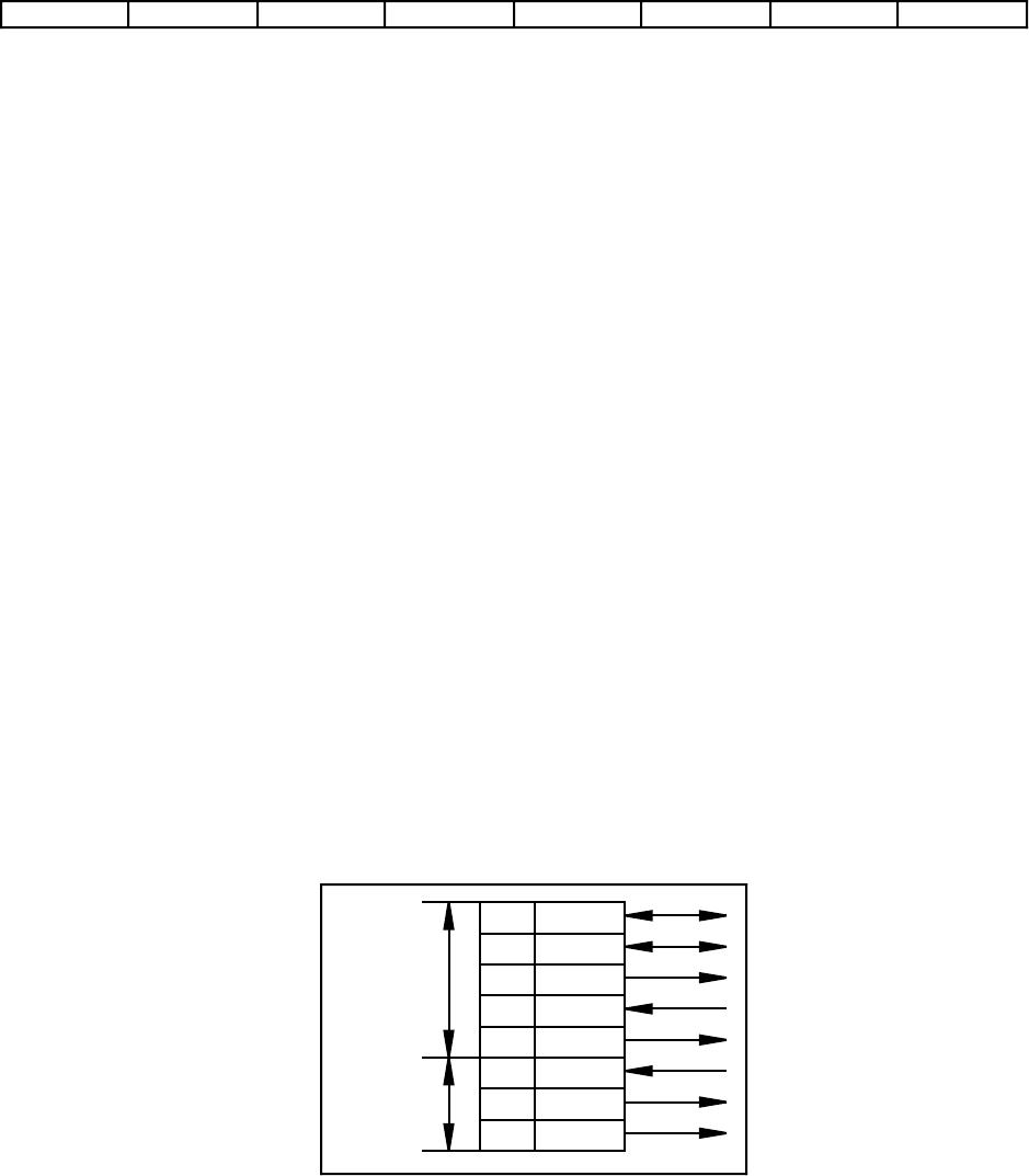
At the digital I/O connector, Port C has the following pin assignments when in Mode 1 input.
Notice that the status of STBA* and STBB* is not provided in the Port C status word.
PC7
PC6
PC5
PC4
PC3
PC2
PC1
PC0
I/O
IBFA
STBA*
INTRA
STBB*
IBFB
INTRB
I/O
Group A
Group B