Register Map and Descriptions Appendix D
Lab-PC+ User Manual D-14 © National Instruments Corporation
Bit Name Description (continued)
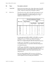
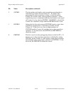
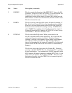
2 ECKDRV This bit controls the direction of the EXTCONV* line on the I/O
Connector. If this bit is clear, EXTCONV* is driven from the I/O
Connector into the conversion circuitry. If this bit is set, a
conditioned version of the output of counter A0 is driven onto the
I/O Connector. Under most circumstances, this bit should be clear.
This bit is cleared on reset.
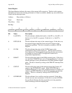
1 EOIRCV This bit is used to select the clock source for interval scanning. If
this bit is clear, Counter B1 drives the interval scanning circuitry.
If this bit is set, the signal present on the OUTB1 line on the I/O
Connector drives the interval scanning circuitry. If INTSCAN is
clear, EOIRCV does nothing more than disconnect the output of
Counter B1 from the I/O Connector–if INTSCAN is clear, always
clear EOIRCV. This bit is cleared on reset.
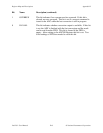
0 INTSCAN This bit selects the DAQ mode. When you set this bit, the
Lab-PC+ performs interval data acquisition. If you clear this bit,
continuous channel scanning is selected. If interval channel
scanning is selected, scan sequences occur during a programmed
time interval, called a scan interval. The duration of the scan
interval is determined by the output of Counter B1 or by the signal
present on the OUTB1 line on the I/O Counter, as determined by
EOIRCV.
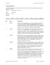
This bit also selects the clock source for Counter B1. If interval
scanning is disabled (INTSCAN = 0), then Counter B1 is available
for user applications. You can then drive CLKB1 externally at the
I/O Connector. If interval scanning is enabled (INTSCAN = 1), the
clock source for Counter A0 also drives CLKB1. The source can
be further selected by using the TBSEL bit in command register 2.
This bit is cleared on reset.


