


Appendix D Register Map and Descriptions
© National Instruments Corporation D-11 Lab-PC+ User Manual
Command Register 3
The Command Register 3 contains six bits that enable and disable the interrupts and DMA
operation.
Address: Base address + 02 (hex)
Type: Write-only
Word Size: 8-bit
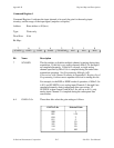
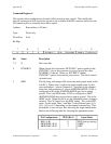
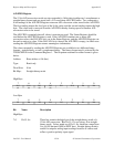
Bit Map:
765 43210
X X FIFOINTEN ERRINTEN CNTINTEN TCINTEN DIOINTEN DMAEN
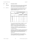
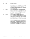
Bit Name Description
7-6 X Don't care bits.
5 FIFOINTEN This bit enables and disables the generation of an interrupt when
A/D conversion results are available. If FIFOINTEN is set, an
interrupt is generated whenever an A/D conversion is available to
be read from the FIFO.
4 ERRINTEN This bit enables and disables the generation of an interrupt when an
A/D error condition is detected. If an A/D error condition occurs,
either OVERFLOW or OVERRUN is set in the Status Register.
The interrupt is serviced by writing to the A/D Clear Register. If
ERRINTEN is cleared, no error interrupts are generated.
3 CNTINTEN This bit enables the Counter A2 output or the EXTUPDATE*
signal to cause interrupts. If this bit is set, an interrupt occurs
when either EXTUPDATE* or Counter A2 output makes a low-to-
high transition. This interrupt is cleared by writing to the Timer
Interrupt Clear Register. This interrupt allows waveform
generation on the analog output because the same signal that sets
the interrupt also updates the DAC output if the corresponding
LDAC bit in Command Register 2 is set. If this bit is cleared,
interrupts from EXTUPDATE* and Counter A2 output are
ignored.
2 TCINTEN This bit enables and disables the generation of an interrupt when a
DMA terminal count pulse is received. If TCINTEN is set, an
interrupt request is generated when the DMA Controller Transfer
Count Register decrements from 0 to FFFF (hex). The interrupt is
serviced by writing to the DMATCINT Clear Register.