


Chapter 3 Signal Connections
© National Instruments Corporation 3-15 Lab-PC+ User Manual
14 PA0
22 PB0
30 PC0
13
DGND
Lab-PC+ Board
Switch
I/O Connector
+5 V
+5 V
LED
TTL Signal
Port B
PB<7..0>
Port A
PA<7..0>
Port C
PC<7..0>
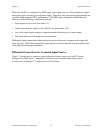
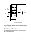
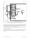
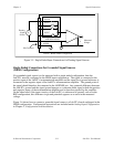
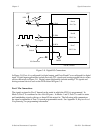
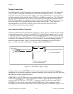
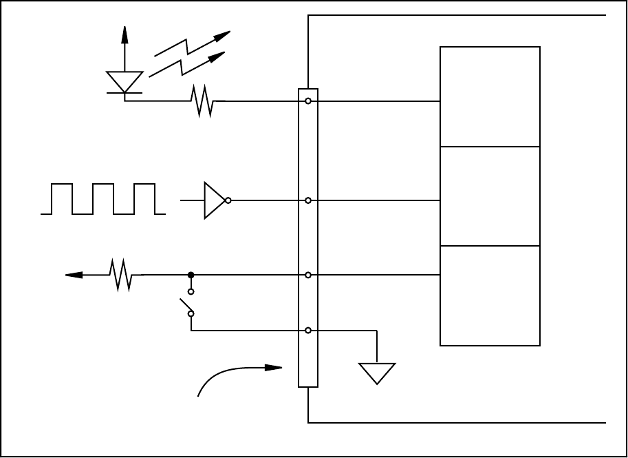
Figure 3-8. Digital I/O Connections
In Figure 3-8, Port A is configured for digital output, and Ports B and C are configured for digital
input. Digital input applications include receiving TTL signals and sensing external device states
such as the switch in Figure 3-8. Digital output applications include sending TTL signals and
driving external devices such as the LED shown in Figure 3-8.
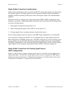
Port C Pin Connections
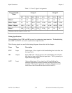
The signals assigned to Port C depend on the mode in which the 8255A is programmed. In
Mode 0, Port C is considered as two 4-bit I/O ports. In Modes 1 and 2, Port C is used for status
and handshaking signals with two or three I/O bits mixed in. The following table summarizes
the signal assignments of Port C for each programmable mode. See Appendix E, Register-Level
Programming, for programming information.