


Appendix E Register-Level Programming
© National Instruments Corporation E-33 Lab-PC+ User Manual
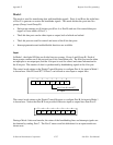
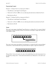
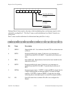
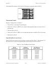
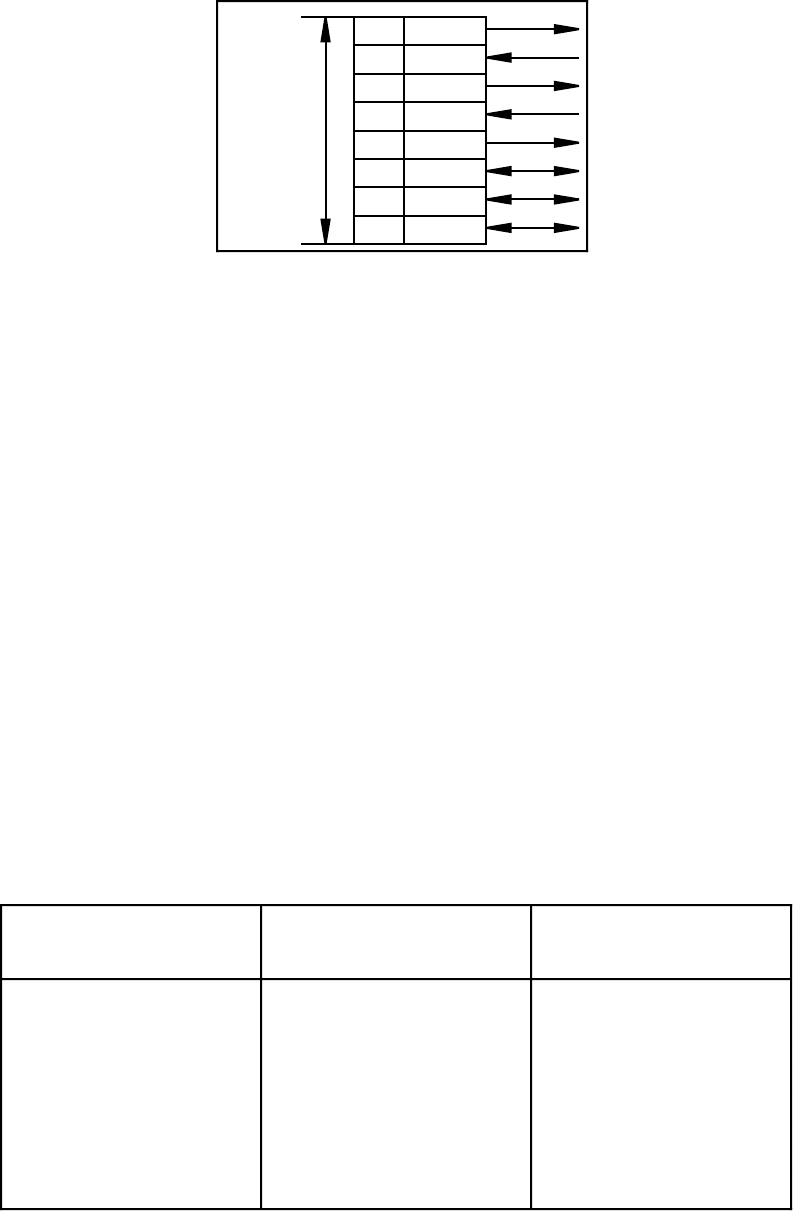
At the digital I/O connector, Port C has the following pin assignments when in Mode 2.
OBFA*PC7
PC6
PC5
PC4
PC3
PC2
PC1
PC0
STBA*
INTRA
IBFA
Group A
ACKA*
I/O
I/O
I/O
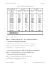
Programming Example
Example. Configure Port A in Mode 2:
• Write C0 (hex) to the Digital Control Register.
• Wait for bit 7 of Port C (OBFA*) to be cleared, indicating that the data last written to Port A
has been read.
• Write new data to Port A.
• Wait for bit 5 of Port C (IBFA) to be set, indicating that data is available in Port A to be read.
• Read data from Port A.
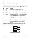
Single Bit Set/Reset Control Words
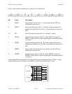
Table E-6 shows the control words for setting or resetting each bit in Port C. Notice that bit 7 of
the control word is cleared for programming the set/reset option for the bits of Port C.
Table E-6. Port C Set/Reset Control Words
Bit Set Bit Reset The Bit Set or
Control Word Control Word Reset in Port C
0xxx0001 0xxx0000 xxxxxxxn
0xxx0011 0xxx0010 xxxxxxnx
0xxx0101 0xxx0100 xxxxxnxx
0xxx0111 0xxx0110 xxxxnxxx
0xxx1001 0xxx1000 xxxnxxxx
0xxx1011 0xxx1010 xxnxxxxx
0xxx1101 0xxx1100 xnxxxxxx
0xxx1111 0xxx1110 nxxxxxxx