


Configuration and Installation Chapter 2
Lab-PC+ User Manual 2-12 © National Instruments Corporation
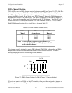
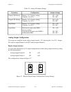
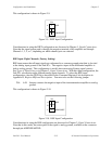
This configuration is shown in Figure 2-9.
W4
•
A
B
C
RSE
NRSE/DIFF
Figure 2-9. DIFF Input Configuration
Considerations in using the DIFF configuration are discussed in Chapter 3, Signal Connections.
Note that the signal return path is through the negative terminal of the amplifier and through
Channels 1, 3, 5, or 7, depending on which channel pair was selected.
RSE Input (Eight Channels, Factory Setting)
RSE input means that all input signals are referenced to a common ground point that is also tied
to the analog input ground of the Lab-PC+. The negative input of the differential amplifier is
tied to analog ground. This configuration is useful when measuring floating signal sources.
See Types of Signal Sources in Chapter 3, Signal Connections. With this input configuration, the
Lab-PC+ can monitor eight different analog input channels. To select the RSE input
configuration, clear the SE__/D bit as described in the Command Register 4 bit description in
Appendix D, Register Map and Descriptions. You must also set the following jumper.
W4: A-B Jumper connects the negative input of the instrumentation amplifier to analog
ground.
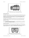
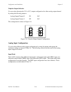
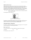
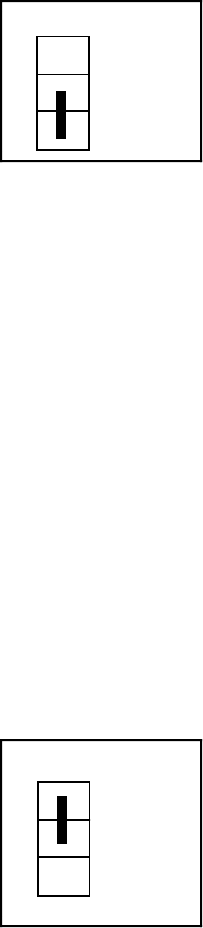
This configuration is shown in Figure 2-10.
W4
•
A
B
C
RSE
NRSE/DIFF
Figure 2-10. RSE Input Configuration
Considerations in using the RSE configuration are discussed in Chapter 3, Signal Connections.
Note that in this mode, the return path of the signal is analog ground, available at the connector
through pin AISENSE/AIGND.