


Specifications Appendix A
Lab-PC+ User Manual A-4 © National Instruments Corporation
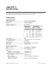
Analog Output
Output Characteristics
Number of channels ...................................... 2
Resolution ..................................................... 12 bits, 1 in 4,096
Type of DAC................................................. Double-buffered multiplying
Data transfers ................................................ Interrupts, programmed I/O
Transfer Characteristics
Relative accuracy (INL)................................
bipolar range ........................................... ±0.25 LSB typ, ±0.5 LSB max
DNL .............................................................. ±0.25 LSB typ, ±0.75 LSB max
Monotonicity ................................................. 12 bits, guaranteed
Offset error ....................................................
After calibration ...................................... Adjustable to 0 V
Before calibration.................................... ±37 mV max
Gain error (relative to internal reference)
After calibration ...................................... Adjustable to 0%
Before calibration.................................... ±0.5% of reading (3,900 ppm) max
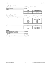
Voltage Output
Ranges ........................................................... ±5 V, or 0 to 10 V, jumper selectable
Output coupling............................................. DC
Output impedance ......................................... 0.2 Ω max
Current drive ................................................. ±2 mA max
Protection ...................................................... Short to AGND
Power on state ............................................... 0 V for ±5 V range, 5 V for 0 to 10 V range
Dynamic Characteristics
Settling time to FSR for 10 V step ................ 5 µs
Slew rate........................................................ 10 V/µs
Stability
Offset temperature coefficient ...................... ±30 µV/°C
Gain temperature coefficient
internal reference..................................... ±10 ppm/°C
Explanation of Analog Output Specifications
Relative accuracy in a D/A system is the same as nonlinearity, because no uncertainty is added
due to code width. Unlike an ADC, every digital code in a D/A system represents a specific
analog value rather than a range of values. The relative accuracy of the system is therefore
limited to the worst-case deviation from the ideal correspondence (a straight line), excepting
noise. If a D/A system has been calibrated perfectly, then the relative accuracy specification
reflects its worst-case absolute error.