


Configuration and Installation Chapter 2
Lab-PC+ User Manual 2-8 © National Instruments Corporation
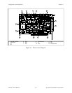
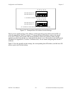
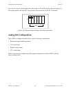
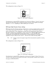
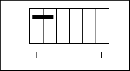
If you do not want to use interrupts, place the jumper on W5 in the position shown in Figure 2-6.
This setting disables the Lab-PC+ from asserting an interrupt line on the PC I/O channel.
•
•
•
•
•
•
•
•
•
•
•
•
IRQ
W5
3 4 5 6 7 9
Figure 2-6. Interrupt Jumper Setting for Disabling Interrupts
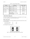
Analog I/O Configuration
The Lab-PC+ is shipped from the factory with the following configuration:
• Referenced single-ended input mode
• ±5 V input range
• Bipolar analog output
• ±5 V output range
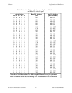
Table 2-4 lists all the available analog I/O jumper configurations for the Lab-PC+ with the
factory settings noted.