


Register-Level Programming Appendix E
Lab-PC+ User Manual E-24 © National Instruments Corporation
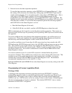
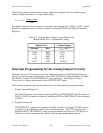
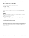
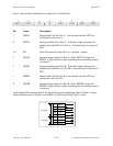
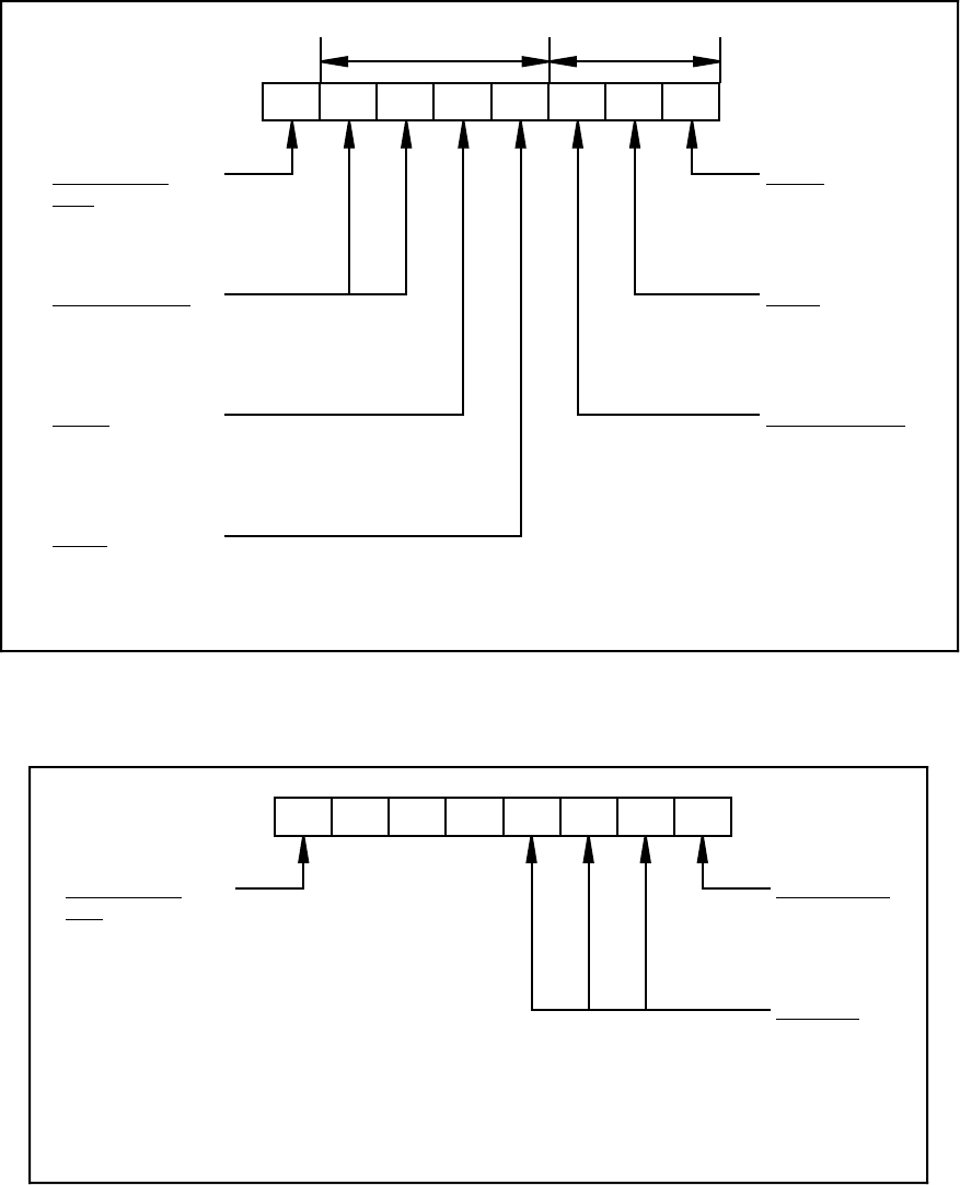
D7 D6 D5 D4 D3 D2 D1 D0
Control-Word
Flag
1 = Mode Set
Mode Selection
00 = Mode 0
01 = Mode 1
1X = Mode 2
Port A
1 = input
0 = output
Port C
(low nibble)
1 = input
0 = output
Port B
1 = input
0 = output
Mode Selection
0 = Mode 0
1 = Mode 1
Group A Group B
Port C
(high nibble)
1 = input
0 = output
Figure E-1. Control-Word Format with Control-Word Flag Set to 1
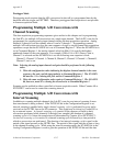
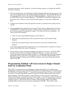
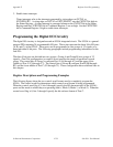
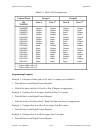
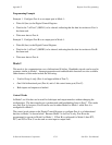
D7 D3 D2 D1 D0
Control-Word
Flag
0 = Bit Set/Reset
Bit Set/Reset
1 = set
0 = reset
Bit Select
(000)
(001)
(010)
:
:
(111)
XXX
Figure E-2. Control-Word Format with Control-Word Flag Set to 0
This section describes the Digital Control Register, which is used to program the 8255A ports in
any one of the three modes discussed earlier in this section. Specific control words for each
mode are described later in this section along with programming examples for each mode.