


Register Map and Descriptions Appendix D
Lab-PC+ User Manual D-16 © National Instruments Corporation
A/D FIFO Register
The 12-bit A/D conversion results are sign-extended to 16-bit data in either two's complement or
straight binary format and are stored into a 512-word deep A/D FIFO buffer. Two consecutive
8-bit readings of the A/D FIFO Register return an A/D conversion value stored in the A/D FIFO.
The first reading returns the low byte of the 16-bit value, and the second reading returns the high
byte. The value read is removed from the A/D FIFO, thereby freeing space for another A/D
conversion value to be stored.
The A/D FIFO is emptied when all values it contains are read. The Status Register should be
read before the A/D FIFO Register is read. If the A/D FIFO contains one or more A/D
conversion values, the DAVAIL bit is set in the Status Register, and the A/D FIFO Register can
be read to retrieve a value. If the DAVAIL bit is cleared, the A/D FIFO is empty, in which case
reading the A/D FIFO Register returns meaningless information.
The values returned by reading the A/D FIFO Register are available in two different binary
formats: straight binary or two's complement binary. The binary format used is selected by the
TWOSCMP bit in the Command Register 1. The bit pattern returned for either format is given
below.
Address: Base address + 0A (hex)
Type: Read-only
Word Size: 8-bit
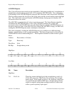
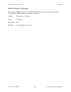
Bit Map: Straight binary mode
High Byte
76543210
D15 D14 D13 D12 D11 D10 D9 D8
(0) (0) (0) (0)
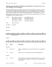
Low Byte
76543210
D7 D6 D5 D4 D3 D2 D1 D0
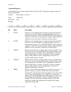
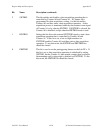
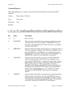
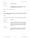
Bit Name Description
High Byte
7-0 D<15..8> These bits contain the high byte of the straight binary result of a
12-bit A/D conversion. Bits D<15..12> are always 0 in straight
binary mode. Values made up of D<11..0>, therefore, range from
0 to +4,095 decimal (0000 to 0FFF hex). Straight binary mode is
useful for unipolar analog input readings because all values read
reflect a positive polarity input signal.