


Chapter 2 Configuration and Installation
© National Instruments Corporation 2-3 Lab-PC+ User Manual
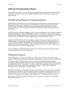
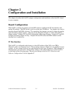
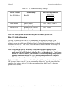
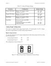
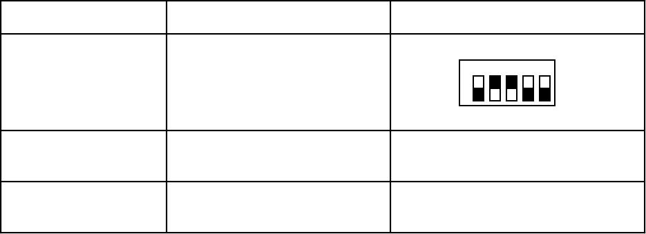
Table 2-1. PC Bus Interface Factory Settings
Lab-PC+ Board Default Settings Hardware Implementation
Base I/O Address Hex 260
A5
1 2 3 4 5
O
N
O
F
F
U1
A9
A8
A7
A6
DMA Channel DMA Channel 3
(factory setting)
W6: DRQ3, DACK*3
Interrupt Level Interrupt level 5 selected
(factory setting)
W5: Row 5
Note: The shaded portion indicates the side of the switch that is pressed down.
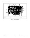
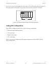
Base I/O Address Selection
The base I/O address for the Lab-PC+ is determined by the switches at position U1 (see
Figure 2-1). The switches are set at the factory for the base I/O address hex 260. This factory
setting is used as the default base I/O address value by National Instruments software packages
for use with the Lab-PC+. The Lab-PC+ uses the base I/O address space hex 260 through 27F
with the factory setting.
Note: Verify that this space is not already used by other equipment installed in your
computer. If any equipment in your computer uses this base I/O address space, you
must change the base I/O address of the Lab-PC+ or of the other device. If you change
the Lab-PC+ base I/O address, you must make a corresponding change to any software
packages you use with the Lab-PC+. For more information about your computer’s
I/O, refer to your computer’s technical reference manual.
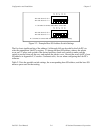
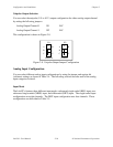
Each switch in U1 corresponds to one of the address lines A9 through A5. Press the side marked
OFF to select a binary value of 1 for the corresponding address bit. Press the other side of the
switch to select a binary value of 0 for the corresponding address bit. Figure 2-2 shows two
possible switch settings.