


Register Map and Descriptions Appendix D
Lab-PC+ User Manual D-6 © National Instruments Corporation
Bit Name Description (continued)
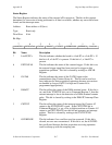
3 TWOSCMP This bit selects the format of the coding of the output of the ADC.
If this bit is set, the 12-bit data from the ADC is sign-extended to
16 bits. If this bit is cleared, bits 12 through 15 return 0.
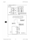
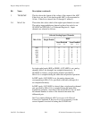
2-0 MA<2..0> These three bits select which of the eight input channels are read.
The analog input multiplexers depend on these bits and also on
SCANEN and SE
__
/D (bit 3 of Command Register 4). Input
channels are selected as follows:
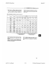
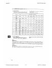
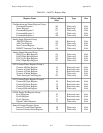
Selected Analog Input Channels
MA<2..0> Single-Ended
DIFF
Scan Disabled Scan Enabled
(+) (-) (+) (-)
000 0 0 1 0 1
001 1 0 1 2 3
010 2 2 3 4 5
011 3 2 3 6 7
100 4 4 5 0 1
101 5 4 5 2 3
110 6 6 7 4 5
111 7 6 7 6 7
In single-ended mode (RSE or NRSE), if SCANEN is set, analog
channels MA<2..0> through 0 are sampled alternatively. If
SCANEN is cleared, a single analog channel specified by
MA<2..0> is sampled during the entire data acquisition operation.
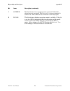
In DIFF mode, if SCANEN is set, the analog channel pair
corresponding to MA<2..0>, specified in the table, through (0,1)
are sampled alternately.
In DIFF mode, if SCANEN is cleared, then a single analog channel
pair specified by MA<2..0> is sampled during the entire data
acquisition operation. Note that in this mode, MA<2..0> can hold
the channel number of either of the channels that make the
differential pair.
See Programming Multiple A/D Conversions with Channel
Scanning in Appendix E, Register-Level Programming, for the
correct sequence involved in setting the SCANEN bit.