


© National Instruments Corporation 2-1 Lab-PC+ User Manual
Chapter 2
Configuration and Installation
This chapter describes the Lab-PC+ jumper configuration and installation of the Lab-PC+ board
in your computer.
Board Configuration
The Lab-PC+ contains six jumpers and one DIP switch to configure the PC bus interface and
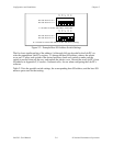
analog I/O settings. The DIP switch is used to set the base I/O address. Two jumpers are used as
interrupt channel and DMA selectors. The remaining four jumpers are used to change the analog
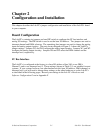
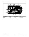
input and analog output circuitry. The parts locator diagram in Figure 2-1 shows the Lab-PC+
jumper settings. Jumpers W3 and W4 configure the analog input circuitry. Jumpers W1 and W2
configure the analog output circuitry. Jumpers W6 and W5 select the DMA channel and the
interrupt level, respectively.
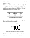
PC Bus Interface
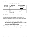
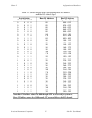
The Lab-PC+ is configured at the factory to a base I/O address of hex 260, to use DMA
Channel 3, and to use interrupt level 5. These settings (shown in Table 2-1) are suitable for most
systems. If your system, however, has other hardware at this base I/O address, DMA channel, or
interrupt level, you will need to change these settings on the other hardware or on the Lab-PC+
as described in the following pages. Record your settings in the Lab-PC+ Hardware and
Software Configuration Form in Appendix F.