


Signal Connections Chapter 3
Lab-PC+ User Manual 3-24 © National Instruments Corporation
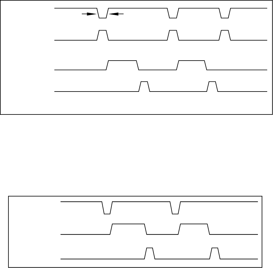
t
ext
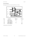
Minimum 50 nsec
EXTUPDATE*
DAC OUTPUT
UPDATE
CNTINT
DACWRT
t
ext
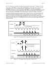
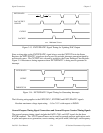
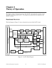
Figure 3-13. EXTUPDATE* Signal Timing for Updating DAC Output
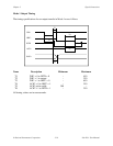
Since a rising edge on the EXTUPDATE* signal always sets the CNTINT bit in the Status
Register, the EXTUPDATE* signal can also be used for periodic interrupt generation timed by
an external source. The CNTINT bit is cleared by writing to the Timer Interrupt Clear Register.
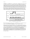
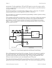
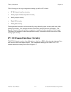
Figure 3-14 illustrates a timing sequence where EXTUPDATE* is being used to generate an
interrupt.
EXTUPDATE*
CNTINT
TMRINTCLR
Figure 3-14. EXTUPDATE* Signal Timing for Generating Interrupts
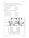
The following rating applies to the EXTCONV*, EXTTRIG and EXTUPDATE* signals.
Absolute maximum voltage input rating: -0.5 to 7.0 V with respect to DGND
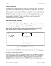
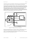
General-Purpose Timing Signal Connections and General-Purpose Counter/Timing Signals
The general-purpose timing signals include the GATE, CLK, and OUT signals for the three
8253(B) counters. The 8253 Counter/Timers can be used for general-purpose applications such
as pulse and square wave generation; event counting; and pulse-width, time-lapse, and frequency