


Register-Level Programming Appendix E
Lab-PC+ User Manual E-32 © National Instruments Corporation
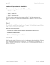
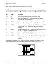
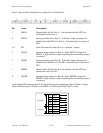
Port B direction
1 = input
0 = output
Group B Mode
0 = Mode 0
1 = Mode 1
1 X X 1/01 1/0X 1/0
765
43210
Port C bits (PC2-PC0)
1 = input
0 = output
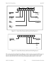
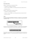
During a Mode 2 data transfer, the status of the handshaking lines and interrupt signals can be
obtained by reading Port C. The Port C status-word bit definitions for a Mode 2 transfer are
shown next.
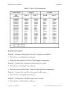
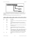
Port C status-word bit definitions for bidirectional data path (Port A only):
76543210
OBFA* INTE1 IBFA INTE2 INTRA I/O I/O I/O
Bit Name Description
7 OBFA* Output buffer full. Low indicates that the CPU has written data out
to Port A.
6 INTE1 Interrupt enable bit for output. If this bit is set, interrupts are
enabled from the 8255A for OBF*. Controlled by bit set/reset of
PC6.
5 IBFA Input buffer full. High indicates that data has been loaded into the
input latch of Port A.
4 INTE2 Interrupt enable bit for input. If this bit is set, interrupts are
enabled from the 8255A for IBF. Controlled by bit set/reset of
PC4.
3 INTRA Interrupt request status. If INTE1 is high and IBFA is high, this bit
is high, indicating that an interrupt request is asserted for input
transfers. If INTE2 is high and OBFA* is high, this bit is high,
indicating that an interrupt request is asserted for output transfers.
2-0 I/O Extra I/O status lines available if Port B is not configured for
Mode 1.