


Signal Connections Chapter 3
Lab-PC+ User Manual 3-26 © National Instruments Corporation
counting after receiving a low-to-high edge. The time lapse since receiving the edge equals the
counter value difference (loaded value minus read value) multiplied by the CLK period.
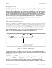
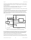
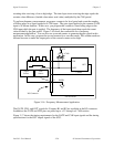
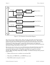
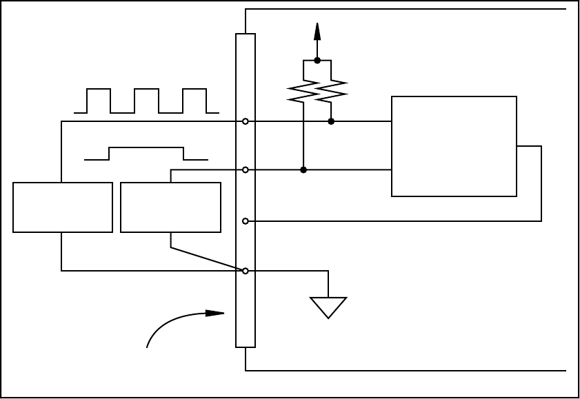
To perform frequency measurement, program a counter to be level gated and count the number
of falling edges in a signal applied to a CLK input. The gate signal applied to the counter GATE
input is of known duration. In this case, you program the counter to count falling edges at the
CLK input while the gate is applied. The frequency of the input signal then equals the count
value divided by the gate period. Figure 3-16 shows the connections for a frequency
measurement application. You can also use a second counter to generate the gate signal in this
application. In this case, program the second counter for a one-shot mode. This scheme needs an
external inverter to make the output pulse of the second counter active high.
+5 V
I/O Connector
CLK
GATE
OUT
DGND
Lab-PC Board
Gate
Source
Signal
Source
Counter
4.7 kΩ
13
Figure 3-16. Frequency Measurement Application
The GATE, CLK, and OUT signals for Counters B1 and B2 are available at the I/O connector.
In addition, the GATE and CLK pins are pulled up to +5 V through a 4.7 kΩ resistor.
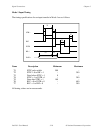
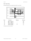
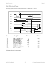
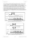
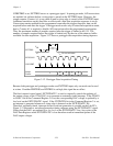
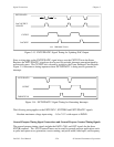
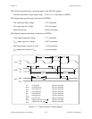
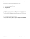
Figure 3-17 shows the timing requirements for the GATE and CLK input signals and the timing
specifications for the OUT output signals of the 8253.