


Theory of Operation Chapter 4
Lab-PC+ User Manual 4-6 © National Instruments Corporation
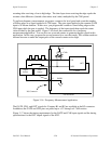
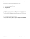
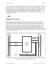
(scanned) data acquisition in two modes–continuous and interval. The Lab-PC+ uses a counter
to switch between analog input channels automatically during scanned data acquisition.
Data acquisition timing consists of signals that initiate a data acquisition operation, initiate
individual A/D conversions, gate the data acquisition operation, and generate scanning clocks.
Sources for these signals are supplied mainly by timers on the Lab-PC+ board. One of the two
8253 integrated circuits is reserved for this purpose.
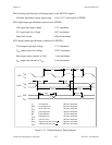
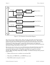
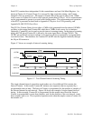
An A/D conversion can be initiated by a high-to-low transition on the Counter A0 output (OUT
A0) of the 8253(A) Counter/Timer chip on the Lab-PC+ or by a high-to-low transition on
EXTCONV* input. During data acquisition, the onboard sample interval counter–Counter 0 of
8253(A)–is used to generate pulses that initiate A/D conversions.
The sample interval timer is a 16-bit down counter that uses the 1 MHz clock onboard to
generate sample intervals from 2 µs to 65,535 µs (see Timing I/O Circuitry later in this chapter).
Alternatively, the sample interval timer can use the output from Counter B0 (OUTB0) of the
8253(B) Counter/Timer chip on the Lab-PC+. Each time the sample interval timer reaches 0, it
generates a pulse and reloads with the programmed sample interval count. This operation
continues until the counter is reprogrammed.
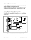
As stated in Appendix E, Register-Level Programming, only Counter A0 is required for data
acquisition operations in freerun acquisition mode. The software must keep track of the number
of conversions that have occurred and turn off Counter A0 after the required number of
conversions have been obtained. In controlled acquisition mode, two counters (Counters A0 and
A1) are required for a data acquisition operation. Counter A0 generates the conversion pulses,
and Counter A1 gates off Counter A0 after the programmed count has expired.
Single-Channel Data Acquisition
During single-channel data acquisition, the channel select and gain bits in Command Register 1
select the gain and analog input channel before data acquisition is initiated. These gain and
multiplexer settings remain constant during the entire data acquisition process; therefore, all A/D
conversion data is read from a single channel.
Multiple-Channel (Scanned) Data Acquisition
Multiple-channel data acquisition is performed by enabling scanning during data acquisition.
Multiple-channel scanning is controlled by a scan counter.
For scanning operations, the scan counter decrements from the highest numbered channel
(specified by the user) through Channel 0 and then repeats the sequence. Thus, any number of
channels from two to eight can be scanned. Notice that the same gain setting is used for all
channels in the scan sequence.
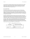
In single-channel continuous acquisition mode, the Lab-PC+ samples a single channel
continuously without delays. In scanned continuous acquisition mode, the Lab-PC+ scans the
selected channels repeatedly without delays and samples them.