


Chapter 5 Calibration
© National Instruments Corporation 5-5 Lab-PC+ User Manual
later for software offset correction of the data at gains other than 1, thus eliminating the need
to perform the input offset recalibration when a different gain is used. The software
correction consists of subtracting the recorded reading at gain G from every A/D conversion
value obtained at gain G.
3. Gain Calibration
Adjust the analog input gain by applying an input voltage across ACH0 and
AISENSE/AIGND. This input voltage is +4.99634 V or V
+fs
- 1.5 LSB.
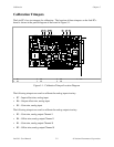
a. Connect the calibration voltage (+4.99634 V) across ACH0 (pin 1 on the
I/O connector) and AISENSE/AIGND (pin 9).
b. Take analog input readings from Channel 0 at a gain of 1, and adjust trimpot R5 until the
ADC readings flicker evenly between 2,046 and 2,047. Alternatively, you can average a
number of readings (approximately 100) and adjust trimpot R10 until the average reading
is 2,046.5.
Unipolar Input Calibration Procedure
If your board is configured for unipolar input, which has an input range of 0 to +10 V, then
complete the following steps in sequence. This procedure assumes that ADC readings are in the
range 0 to 4,095, that is, the TWOSADC bit in Command Register 1 is cleared. The following
should be performed with the input configuration set to RSE.
1. Input Offset Calibration
To adjust the amplifier input offset:
a. Connect ACH0 (pin 1 on the I/O connector) to AISENSE/AIGND (pin 9).
b. Take analog input readings from Channel 0 at gains of 1 and 50.
c. Adjust trimpot R7 until the readings match to within one count at both gain settings.
2. Output Offset Calibration
To adjust the amplifier output offset:
a. Connect ACH0 (pin 1 on the I/O connector) to AISENSE/AIGND (pin 9).
b. Take analog input readings from Channel 0 at the gain at which the system will be used.
c. Adjust trimpot R6 until the readings flicker between 0 and 1. Care must be taken to
avoid setting the potentiometer too low in the unipolar mode. If the potentiometer is set
too low, the ADC then simply outputs 0 because its input is below the lower limit.