


Appendix E Register-Level Programming
© National Instruments Corporation E-3 Lab-PC+ User Manual
Analog Input Circuitry Programming Sequence
Programming the analog input circuitry for a single A/D conversion involves selecting the analog
input channel and gain, initiating an A/D conversion, and reading the A/D conversion result.
1. Select analog input channel and gain.
The analog input channel and gain are selected by writing to Command Register 1. See the
Command Register 1 bit description earlier in this chapter for gain and analog input channel
bit patterns. Set up the bits as given in the Command Register 1 bit description, and write to
the Command Register 1.
Command Register 1 needs to be written to only when the analog input channel, gain setting,
input mode (unipolar/bipolar), or scanning mode need to be changed.
2. Initiate an A/D conversion.
An A/D conversion can be initiated by an active low pulse on the Counter A0 output
(OUTA0) or on the EXTCONV* line. To enable Counter A0 and the EXTCONV*, the
SWTRIG bit in Command Register 2 must be set and OUTA1 must be low. Alternatively, a
conversion can be performed by writing to the Start Convert Register.
Once an A/D conversion is initiated, the ADC stores the result in the A/D FIFO at the end of
its conversion cycle or after a rising edge on OUTA0, whichever occurs later. In case of
EXTCONV* initiating the conversion, OUTA0 must be set high.
3. Read the A/D conversion result.
A/D conversion results are obtained by reading the A/D FIFO Register. Before you read the
A/D FIFO, however, you must read the Status Register to determine whether the A/D FIFO
contains any results.
To read the A/D conversion results, complete these steps:
a. Read the Status Register (8-bit read).
b. If the DAVAIL bit is set (bit 0), then read the A/D FIFO Register twice to obtain the
result. The first reading returns the low byte of 16-bit data, and the second reading
returns the high byte.
Reading the A/D FIFO Register removes the A/D conversion result from the A/D FIFO. The
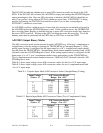
binary modes of the A/D FIFO output are explained in the next section, A/D FIFO Output Binary
Modes.