


Appendix E Register-Level Programming
© National Instruments Corporation E-29 Lab-PC+ User Manual
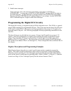
Programming Example
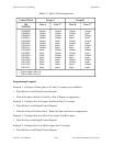
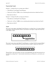
Example 1. Configure Port A as an input port in Mode 1:
• Write B0 (hex) to the Digital Control Register.
• Wait for bit 5 of Port C (IBFA) to be set, indicating that data has been latched into Port A.
• Read data from Port A.
Example 2. Configure Port B as an input port in Mode 1:
• Write 86 (hex) to the Digital Control Register.
• Wait for bit 1 of Port C (IBFB) to be set, indicating that data has been latched into Port B.
• Read data from Port B.
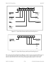
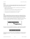
Output
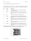
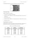
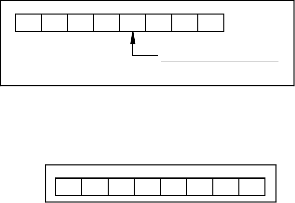
The control word written to the Digital Control Register to configure Port A for output in Mode 1
is shown here. Bits PC4 and PC5 of Port C can be used as extra input or output lines when Port
A uses Mode 1 output.
Port C bits PC4 and PC5
1 = input
0 = output
10XXX0 1/01
765
43210
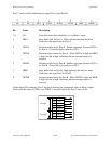
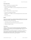
The control word written to the Digital Control Register to configure Port B for output in Mode 1
is shown here. Notice that Port B is not provided with extra input or output lines from Port C.
1X0XXX1X
765
43210
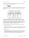
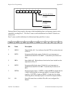
During a Mode 1 data write transfer, the status of the handshaking lines and interrupt signals can
be obtained by reading Port C. Notice that the bit definitions are different for a write and a read
transfer.