


Appendix E Register-Level Programming
© National Instruments Corporation E-27 Lab-PC+ User Manual
Mode 1
This mode is used for transferring data with handshake signals. Ports A and B use the eight lines
of Port C to generate or receive the handshake signals. This mode divides the ports into two
groups (Group A and Group B).
• Each group contains one 8-bit data port (Port A or Port B) and one 4-bit control/data port
(upper or lower nibble of Port C).
• The 8-bit data ports can be either input or output, both of which are latched.
• The 4-bit ports are used for control and status of the 8-bit data ports.
• Interrupt generation and enable/disable functions are available.
Input
In Mode 1, the digital I/O bits are divided into two groups: Group A and Group B. Each of
these groups contains one 8-bit port and one 4-bit control/data port. The 8-bit port can be either
an input port or an output port, and the 4-bit port is used for control and status information for
the 8-bit port. The transfer of data is synchronized by handshaking signals in the 4-bit port.
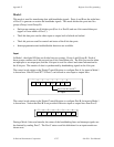
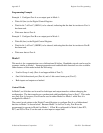
The control word written to the Digital Control Register to configure Port A for input in Mode 1
is shown here. Bits PC6 and PC7 of Port C can be used as extra input or output lines.
Port C bits PC6 and PC7
1 = input
0 = output
10XXX1 1/01
765
43210
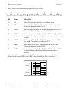
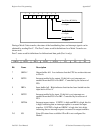
The control word written to the Digital Control Register to configure Port B for input in Mode 1
is shown here. Notice that Port B is not provided with extra input or output lines from Port C.
1X1XXX1X
765
43210
During a Mode 1 data read transfer, the status of the handshaking lines and interrupt signals can
be obtained by reading Port C. The Port C status-word bit definitions for an input transfer are
shown next.