


Signal Connections Chapter 3
Lab-PC+ User Manual 3-4 © National Instruments Corporation
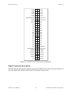
The connector pins can be grouped into analog input signal pins, analog output signal pins,
digital I/O signal pins, and timing I/O signal pins. Signal connection guidelines for each of these
groups are included later in this chapter.
Analog Input Signal Connections
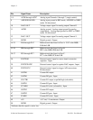
Pins 1 through 8 are analog input signal pins for the 12-bit ADC. Pin 9, AISENSE/AIGND, is
an analog common signal. This pin can be used for a general analog power ground tie to the
Lab-PC+ in RSE mode, or as a return path in DIFF or NRSE mode. Pins 1 through 8 are tied to
the eight single-ended analog input channels of the input multiplexer through 4.7 kΩ series
resistances. Pins 2, 4, 6, and 8 are also tied to an input multiplexer for DIFF mode. Pin 40 is
EXTCONV* and can be used to trigger conversions. A conversion occurs when this signal
makes a high-to-low transition.
The following input ranges and maximum ratings apply to inputs ACH<0..7>:
Input signal range Bipolar input: ±(5/gain) V
Unipolar input: 0 to (10/gain) V
Maximum input voltage rating ±45 V powered on or off
Exceeding the input signal range for gain settings greater than 1 will not damage the input
circuitry as long as the maximum input voltage rating of ±45 V is not exceeded. For example
with a gain of 10, the input signal range is ±0.5 V for bipolar input and 0 to 1V for unipolar
input, but the Lab-PC+ is guaranteed to withstand inputs up to the maximum input voltage rating.
Warning: Exceeding the input signal range results in distorted input signals. Exceeding the
maximum input voltage rating may cause damage to the Lab-PC+ board and to
the computer. National Instruments is
NOT liable for any damages resulting from
such signal connections.
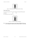
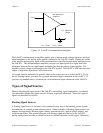
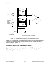
Connection of analog input signals to the Lab-PC+ depends on the configuration of the Lab-PC+
analog input circuitry and the type of input signal source. With the different Lab-PC+
configurations, the Lab-PC+ instrumentation amplifier can be used in different ways. Figure 3-2
shows a diagram of the Lab-PC+ instrumentation amplifier.