


Appendix E Register-Level Programming
© National Instruments Corporation E-21 Lab-PC+ User Manual
updated when a low level is detected on either EXTUPDATE* or OUTA2. If LDAC0 is set low,
the analog output from DAC0 is updated as soon as the DAC0 Data Register is written to.
LDAC1 controls the updating of DAC1 analog output in a similar manner.
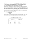
The output voltage generated from the digital code depends on the configuration, unipolar or
bipolar, of the associated analog output channel. Unipolar or bipolar configuration is determined
by jumper settings described in Chapter 2, Configuration and Installation. Table E-3 shows the
output voltage versus digital code for a unipolar analog output configuration. Table E-4 shows
the voltage versus digital code for a bipolar analog output configuration.
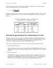
The following formula calculates the voltage output versus digital code for a unipolar analog
output configuration and straight binary coding:
V
out
= 10.0
*
(digital code)
4,096
The digital code in the preceding formula is a decimal value ranging from 0 to +4,095. Notice
that straight binary coding is selected by clearing the 2SDAC bit in Command Register 2.
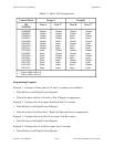
Table E-3. Analog Output Voltage Versus Digital Code
(Unipolar Mode, Straight Binary Coding)
Digital Code Voltage Output
(Decimal) (Hex)
0 0000 0 V
1 0001 2.4414 mV
2,048 0800 5.0 V
4,095 0FFF 9.9976 V