


Configuration and Installation Chapter 2
Lab-PC+ User Manual 2-10 © National Instruments Corporation
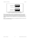
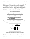
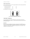
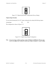
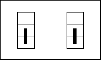
Unipolar Output Selection
You can select the unipolar (0 V to 10 V) output configuration for either analog output channel
by setting the following jumpers:
Analog Output Channel 0 W1 B-C
Analog Output Channel 1 W2 B-C
This configuration is shown in Figure 2-8.
•
•
•
A
B
C
W1
Channel 0
B
U
•
•
•
A
B
C
W2
Channel 1
B
U
Figure 2-8. Unipolar Output Jumper Configuration
Analog Input Configuration
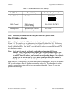
You can select different analog input configurations by using the jumper and register bit
(software) settings as shown in Table 2-4. The following sections describe each of the analog
input categories in detail.
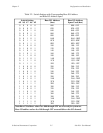
Input Mode
The Lab-PC+ features three different input modes–referenced single-ended (RSE) input, non-
referenced single-ended (NRSE) input, and differential (DIFF) input. The single-ended input
configurations use eight channels. The DIFF input configuration uses four channels. These
configurations are described in Table 2-5.