


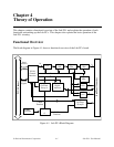
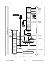

Theory of Operation Chapter 4
Lab-PC+ User Manual 4-8 © National Instruments Corporation
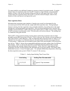
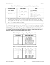
Table 4-2. Lab-PC+ Maximum Recommended Data Acquisition Rates
Acquisition Mode Gain Setting Rate
Single Channel 1
2, 5, 10, 20, 50, 100
83.3 ksamples/s
71.4 ksamples/s*
Multiple Channel 1
2, 5, 10, 20, 50
100
83.3 ksamples/s
62.5 ksamples/s typical,
55.5 ksamples/s worst case
20.0 ksamples/s
* The single-channel acquisition rate decreases at higher gains because an offset error,
dependent on the sampling rate, occurs at rates faster than 71.4 ksamples/s. This offset
error is of the order of 1 LSB. If you can tolerate the offset error, the maximum sampling
rate of 83.3 ksamples/s applies at all gains.
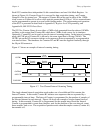
The recommended data acquisition rates given in Table 4-2 assume that voltage levels on all the
channels included in the scan sequence are within range for the given gain and are driven by low-
impedance sources. The signal ranges for the possible gains are shown in Table 4-3 and
Table 4-4. Signal levels outside the ranges shown in Table 4-3 on the channels included in the
scan sequence adversely affect the input settling time. Similarly, greater settling time may be
required for channels driven by high-impedance signal sources.
Table 4-3. Bipolar Analog Input Signal Range Versus Gain
Gain Setting Input Signal Range
1 -5 V to 4.99756 V
2 -2.5 V to 2.49878 V
5 -1.0 V to 0.99951 V
10 -500 mV to 499.756 mV
20 -250 mV to 249.877 mV
50 -100 mV to 99.951 mV
100 -50 mV to 49.975 mV
Table 4-4. Unipolar Analog Input Signal Range Versus Gain
Gain Setting Input Signal Range
1 0 V to 9.99756 V
2 0 V to 4.99878 V
5 0 V to 1.99951 V
10 0 mV to 999.756 mV
20 0 mV to 499.877 mV
50 0 mV to 199.951 mV
100 0 mV to 99.975 mV