


Chapter 3 Signal Connections
© National Instruments Corporation 3-25 Lab-PC+ User Manual
measurement. For these applications, CLK and GATE signals are sent to the counters, and the
counters are programmed for various operations. The single exception is counter B0, which has
an internal 2 MHz clock.
The 8253 Counter/Timer is described briefly in Chapter 4, Theory of Operation. For detailed
programming information, consult Appendix B, OKI 82C53 Data Sheet.
Pulse and square wave generation are performed by programming a counter to generate a timing
signal at its OUT output pin.
Event counting is performed by programming a counter to count rising or falling edges applied to
any of the 8253 CLK inputs. The counter value can then be read to determine the number of
edges that have occurred. Counter operation can be gated on and off during event counting.
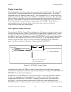
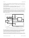
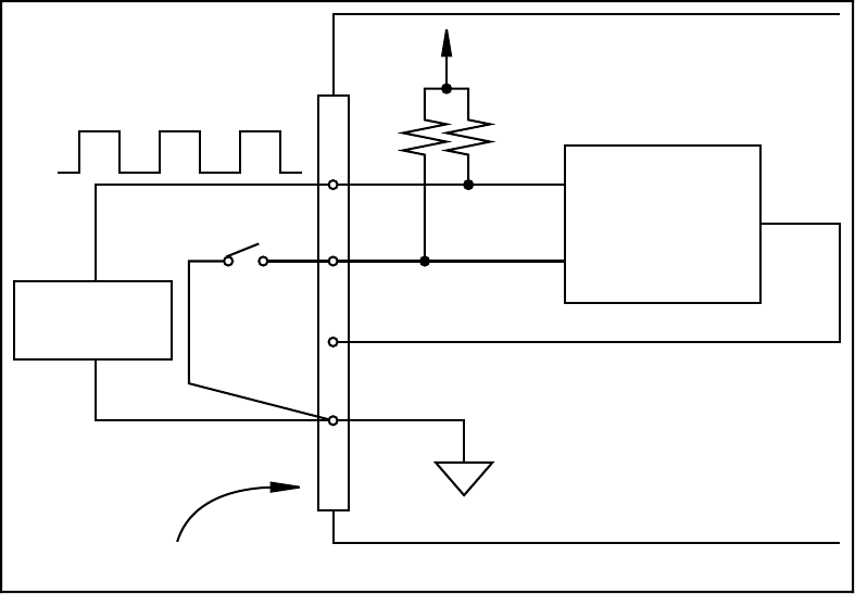
Figure 3-15 shows connections for a typical event-counting operation where a switch is used to
gate the counter on and off.
+5 V
I/O Connector
CLK
GATE
OUT
DGND
Lab-PC Board
Counter (from Group B)
4.7 kΩ
13
Signal
Source
Switch
Figure 3-15. Event-Counting Application with External Switch Gating
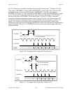
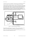
Pulse-width measurement is performed by level gating. The pulse to be measured is applied to
the counter GATE input. The counter is loaded with the known count and is programmed to
count down while the signal at the GATE input is high. The pulse width equals the counter
difference (loaded value minus read value) multiplied by the CLK period.
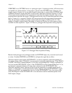
Time-lapse measurement is performed by programming a counter to be edge gated. An edge is
applied to the counter GATE input to start the counter. The counter can be programmed to start