


Appendix E Register-Level Programming
© National Instruments Corporation E-7 Lab-PC+ User Manual
3. Program Counters A0 and A1.
This step involves programming Counter A0 (the sample interval counter) in rate generator
mode (Mode 2) and programming Counter A1 to interrupt on terminal count mode (Mode 0).
Counter A0 of the 8253(A) Counter/Timer is used as the sample interval counter. A high-to-
low transition on the Counter A0 output initiates a conversion. Counter A0 can be
programmed to generate a pulse once every N µs. N is referred to as the sample interval, that
is, the time between successive A/D conversions. N can be between 2 and 65,535. The
sample interval is equal to the period of the timebase clock used by Counter A0 multiplied by
N. Two timebases are available: a 1 MHz clock and the output of Counter B0.
Counter A1 of the 8253(A) Counter/Timer is used as a sample counter. The sample counter
tallies the number of A/D conversions initiated by Counter A0 and stops Counter A0 when
the desired sample count is reached. The sample count must be less than or equal to 65,535.
The minimum sample count is 3.
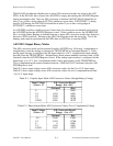
Use the following programming sequence to program the sample interval counter. All writes
are 8-bit write operations. All values given are hexadecimal.
a. Write 34 to the Counter A Mode Register (select Counter A0, Mode 2).
b. Write the least significant byte of the sample interval to the Counter A0 Data Register.
c. Write the most significant byte of the sample interval to the Counter A0 Data Register.
Use the following sequence to program the sample counter:
a. Write 70 to the Counter A Mode Register (select Counter A1, Mode 0).
b. Write the least significant byte of (M-2), where M is the sample count, to the Counter A1
Data Register.
c. Write the most significant byte of (M-2), where M is the sample count, to the Counter A1
Data Register.
After you complete this programming sequence, Counter A1 is configured to count A/D
conversion pulses and Counter A0 output is in a high state.
4. Clear the A/D circuitry.
Before the data acquisition operation is started, the A/D FIFO must be emptied in order to
clear out any old A/D conversion results. This emptying must be performed after the
counters are programmed in case any spurious edges were caused while programming the
counters. Write 0 to the A/D Clear Register to empty the FIFO (8-bit write), followed by two
8-bit reads from the A/D FIFO. Ignore the data obtained in the read.
5. Start and service the data acquisition operation.
To start the data acquisition operation, set the SWTRIG bit in Command Register 2. This
enables Counter A0 to start counting.