


Calibration Chapter 5
Lab-PC+ User Manual 5-2 © National Instruments Corporation
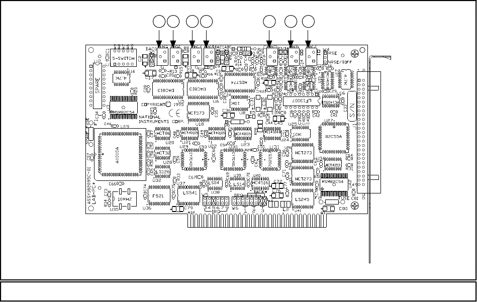
Calibration Trimpots
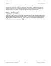
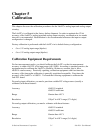
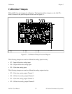
The Lab-PC+ has six trimpots for calibration. The location of these trimpots on the Lab-PC+
board is shown in the partial diagram of the board in Figure 5-1.
1 2 3 4 5 6 7
1R1 3R3 5R5 7R7
2R2 4R4 6R6
Figure 5-1. Calibration Trimpot Location Diagram
The following trimpots are used to calibrate the analog input circuitry:
• R7 – Input offset trim, analog input
• R6 – Output offset trim, analog input
• R5 – Gain trim, analog input
The following trimpots are used to calibrate the analog output circuitry:
• R3 – Gain trim, analog output Channel 1
• R4 – Offset trim, analog output Channel 1
• R1 – Gain trim, analog output Channel 0
• R2 – Offset trim, analog output Channel 0