


Bus Controller (BC)
8-15
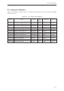
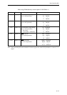
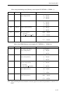
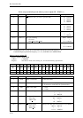
When using handshaking mode (Memory control register 2B B2DRAM = 0, B2WM = 1)
Bit No. Bit name Description Setting conditions
1 to 0 BCS1 to 0 DK detection wait cycle 00: prohibited
(use as DW parameter) 01: 1MCLK
10: 2MCLK
11: 3MCLK
3 to 2 EA1 to 0 RE/WE assert timing 00: prohibited
01: 1MCLK
10: 2MCLK
11: 3MCLK
5 to 4 ADE1 to 0 Address output end timing 00: 0MCLK
11: 3MCLK
10 to 6 BCE4 to 0 Bus cycle end timing 00000: 0MCLK
Set so that:
BCE ≥ REN, BCE ≥ WEN 11111: 31MCLK
15 to 11 REN4 to 0 RE negate timing 00000: 0MCLK
11111: 31MCLK
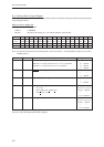
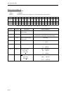
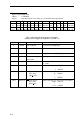
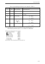
When using DRAM (Memory control register 2B B2DRAM = 1 B2WM = 0)
Bit No. Bit name Description Setting conditions
1 to 0 BCS1 to 0 Row address setup timing 00: prohibited
(use as ASR parameter) 01: 1MCLK
11: 3MCLK
3 to 2 EA1 to 0 Column address setup timing 00: prohibited
(use as ASC parameter) 01: 1MCLK
11: 3MCLK
5 to 4 ADE1 to 0 Column address output timing 00: prohibited
(use as CAO parameter) 01: 1MCLK
Set so that:
CAO (ADE) ≥ ASR (BCS) 11: 3MCLK
8 to 6 BCE2 to 0 RAS hold time 000: prohibited
(use as RSH parameter) 001: 1MCLK
111: 7MCLK
15 to 11 REN4 to 0 CAS pulse width 00000: prohibited
(use as CAS parameter) 00001: 1MCLK
11111: 31MCLK
Note: When performing ICE trace/emulation in software page mode, set the CAS parameter to a value of “5” or
higher.
~
~
~
~
~
~
~
~
~
~
~
~
~
~
~
~